|
|
|
|
1
|
Access the Sequence diagram.
The Interaction pages of the Toolbox display.
|
|
2
|
In the Interaction Relationships page, click on the Message icon, click on the source object and drag the cursor to the destination (target) object.
The Message Properties dialog displays (if not, right-click on the Message and select the Message Properties context menu option).
|
|
3
|
In the field, type the Message name:
| • | If the Message flow is towards a Class element (dropped in from a Class diagram) or a Lifeline element having a classifier, and the destination Class has defined operations, you can click on the drop-down arrow and select an appropriate operation name; the Message then reflects the destination Class operations |
| • | If the available operations are not appropriate, you can click on the button and define a new operation in the target element, using the Operations dialog |
| • | If you create a Message without making reference to the target Class operations, no new operation is added to the target Class |
|
Class Element
Lifeline
Operations Dialog
|
4
|
In the field, type any parameters that the Message has, as a comma-separated list.
If required, in the field type the actual value for each parameter, again as a comma-separated list.
|
|
5
|
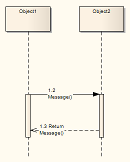
If the Message is a return message, in the field enter the returned value or type.
It is possible to depict returns from a Self Message; simply create a second Self Message at the end of execution and select the checkbox in the Control Flow Type panel.
|
Self-Message
|
6
|
If the Message flow is from a Class element or Lifeline element with classifier that has defined attributes, click on the drop-down arrow in the field and select an appropriate attribute name.
The Message reflects the attributes from the source Class; you cannot add further attributes to the source Class here - if no appropriate attribute is listed, open the element Properties dialog and add the required attribute.
Otherwise, if required, type the name of the object to assign the message flow to.
|
|
7
|
In the field, type or select an optional stereotype for the connector (this is displayed on the diagram, if entered).
|
|
8
|
If required, in the field type an alias for the name of the Message.
On the diagram, the alias displays if the checkbox is selected on the Diagram tab of the Diagram Properties dialog.
The Alias displays instead of or as well as the Message name, depending on the setting selected in the Alias Usage panel of the Diagram Behavior page of the Options dialog.
|
Diagram Behavior Options
|
9
|
In the field, type any conditions that must be true in order for the message to be sent.
|
|
10
|
In the : field in the Control Flow Type panel, select or as appropriate.
|
Asynchronous Signal Message
|
11
|
In the field, select to create a new element at the end of the Message, or to terminate the message flow at the end of the Message.
If neither case applies, leave the field at the default of <none>.
|
|
12
|
If required, in the field type any explanatory notes.
You can format the notes using the Notes toolbar at the top of the field.
|
|
13
|
Click on the button to save the Message definition.
| • | You can change the timing details of a message on the Timing Details dialog, and emphasize the sequence of closely-ordered messages using General Ordering |
| • | To toggle the numbering of messages on a Sequence diagram, select or deselect the Show Sequence Numbering checkbox on the Options dialog
|
|
Change the Timing Details
General Ordering
Sequence diagrams
|