Please note : This help page is not for the latest version of Enterprise Architect. The latest help can be found here.
Communication Diagram
One of four types of Interaction diagram. (The other three are Timing Diagrams, Sequence Diagrams and Interaction Overview Diagrams.)
A Communication diagram shows the interactions between elements at run-time in much the same manner as a Sequence diagram. However, Communication diagrams are used to visualize inter-object relationships, while Sequence diagrams are more effective at visualizing processing over time.
Communication diagrams employ ordered, labeled associations to illustrate processing. Numbering is important to indicate the order and nesting of processing. A numbering scheme could be:
1
1.1
1.1.1
1.1.2
1.2, and so on.
A new number segment begins for a new layer of processing, and would be equivalent to a method invocation.
Robustness diagrams are simplified Communication diagrams, but can be created in any diagram type that supports Boundary, Control and Entity elements.
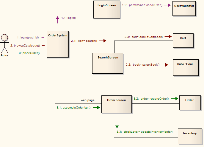
Example Diagram
The example below illustrates a Communication diagram among cooperating object instances. Note the use of message levels to capture related flows, and the different colors of the messages.
Toolbox Elements and Connectors
Select Communication diagram elements and connectors from the Communication pages of the Toolbox.
Tip: |
Click on the following elements and connectors for more information. |
Communication Diagram Elements |
Communication Diagram Connectors |
|
|
|
|
|
|
|
|
|
|
|
|
OMG UML Specification
The OMG UML specification (UML Superstructure Specification, v2.1.1, p. 511) states:
Communication Diagrams focus on the interaction between Lifelines where the architecture of the internal structure and how this corresponds with the message passing is central. The sequencing of Messages is given through a sequence numbering scheme.
Communication Diagrams correspond to simple Sequence Diagrams that use none of the structuring mechanisms such as InteractionUses and CombinedFragments. It is also assumed that message overtaking (i.e., the order of the receptions are different from the order of sending of a given set of messages) will not take place or is irrelevant.
Note: |
Communication diagrams were known as Collaboration diagrams in UML 1.4. |