Please note : This help page is not for the latest version of Enterprise Architect. The latest help can be found here.
Entity Relationship Diagrams (ERDs)
Note: |
Entity Relationship Diagrams are supported in the Corporate, Business and Software Engineering, Systems Engineering and Ultimate editions of Enterprise Architect. |
The following text is derived from the Entity Relationship Model entry in the online Wikipedia:
An entity-relationship model (ERM) is an abstract and conceptual representation of data. Entity-relationship modeling is a database modeling method, used to produce a type of conceptual schema or semantic data model of a system, often a relational database, and its requirements in a top-down fashion. Diagrams created by this process are called Entity-Relationship Diagrams, ER Diagrams, or ERDs.
For further information on the concepts of Entity Relationship Diagrams, refer to the Wikipedia item and its linked sources.
Entity Relationship Diagrams in Enterprise Architect
Entity Relationship Diagrams in Enterprise Architect are based on Chen's ERD building blocks: entities are represented as rectangles, attributes are represented as ellipses and relationships are represented as diamond-shape connectors. ERD technology in Enterprise Architect assists you in every stage from building conceptual data models to generating Data Definition Language (DDL) for the target DBMS.
Enterprise Architect enables you to develop Entity Relationship diagrams quickly and simply, through use of an MDG Technology integrated with the Enterprise Architect installer. The Entity Relationship diagram facilities are provided in the form of:
- An Entity Relationship diagram type, accessed through the New Diagram dialog
- An Entity Relationship Diagram page in the Toolbox
- Entity Relationship element and relationship entries in the Toolbox Shortcut Menu and Quick Linker.
Enterprise Architect also provides transformation templates to transform Entity Relationship Diagrams into Data Modeling Diagrams, and vice versa.
Entity Relationship Diagram Toolbox Page
You can access the Entity Relationship Diagram page of the Toolbox through the More tools | Entity Relationship Diagrams menu option. The following icons are available:
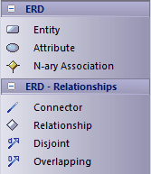
- Entity is an object or concept that is uniquely identifiable. The property of Multiplicity in the SourceRole and TargetRole definitions for the Relationship connector (below) can be used to define the cardinality of an Entity that participates in this relationship.
- Attribute is a property of an entity or a relationship type.
- N-ary Association represents unary (many-to-many recursive) or ternary relationships and can also be used to represent relationships that have attributes among the entities; Note that the N-ary Association element should always be at the target end of a connector.
- Connector is a connector between an Entity and an Attribute, and between two Attributes.
- Relationship is a diamond-shape connector, representing the meaningful association among entities.
- Disjoint and Overlapping represent the relationships between the super-class Entity and the sub-class Entity.
Tagged Values
Some of the Entity Relationship diagram components can be modified by Tagged Values, as indicated below:
Component |
Tagged Value |
Notes |
||
Entity |
isWeakEntity |
If true, this entity is a weak entity. |
||
Attribute |
attributeType |
Four options:
|
||
|
commonDataType |
Defines the common data type for each attribute.
|
||
|
dbmsDataType |
Defines the customized DBMS data type for each attribute.
|
||
N-ary Association |
isRecursive |
If true, the N-ary Association represents the many-to-many recursive relationship. For one-to-many and one-to-one recursive relationships, we suggest using the normal Relationship connector. |
||
Relationship |
isWeak |
If true, the Relationship is a weak relationship. |
||
Disjoin |
Participation |
Two options: partial and total. |
Diagram
A typical Entity Relationship Diagram is represented below:

Tip: |
Sometimes you might want to limit the stretch of the diamond-shape Relationship connectors. Simply pick a Relationship connector, right-click to display the context menu, and select the Bend Line at Cursor option. |
Disable Entity Relationship Diagrams
If you prefer not to use Entity Relationship Diagrams in Enterprise Architect, you can disable it (and subsequently re-enable it) using the MDG Technologies dialog (Settings | MDG Technologies).