Please note : This help page is not for the latest version of Enterprise Architect. The latest help can be found here.
Deployment Diagram
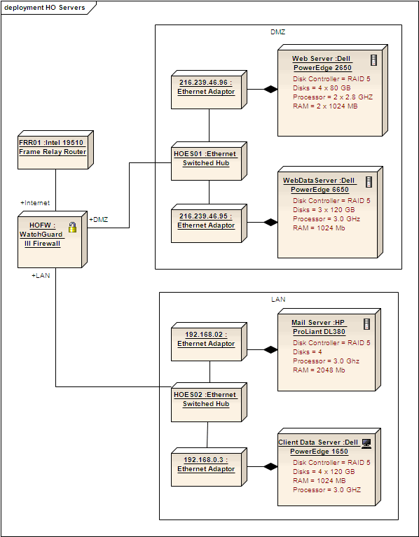
A Deployment diagram shows how and where the system is to be deployed; that is, its execution architecture. Hardware devices, processors and software execution environments (system Artifacts) are reflected as Nodes, and the internal construction can be depicted by embedding or nesting Nodes. Deployment relationships indicate the deployment of Artifacts, and Manifest relationships reveal the physical implementation of components. As Artifacts are allocated to Nodes to model the system's deployment, the allocation is guided by the use of deployment specifications.
A simple Deployment diagram is shown below, representing the arrangement of servers at a head office. The servers are represented by Nodes linked by either simple or aggregate Association relationships.
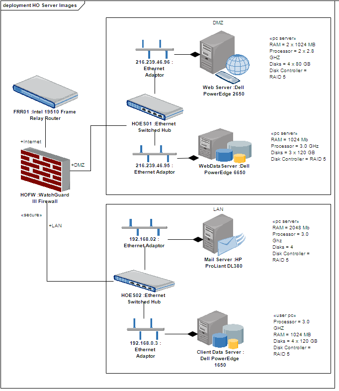
Deployment diagrams are ideal for using alternative images for the objects that the elements represent. Such images can be substituted for the elements in the above diagram, as shown below:
Toolbox Elements and Connectors
Select Deployment diagram elements and connectors from the Deployment pages of the Toolbox.
Tip: |
Click on the following elements and connectors for more information. |
Deployment Diagram Elements |
Deployment Diagram Connectors |
|
|
|
|
|
|
|
|
|
|
|
|
|
|
|
|
|
|