Please note : This help page is not for the latest version of Enterprise Architect. The latest help can be found here.
Use Case Diagram
A Use Case diagram captures Use Cases and relationships between Actors and the subject (system). It describes the functional requirements of the system, the manner in which outside things (Actors) interact at the system boundary, and the response of the system.
In developing a Use Case diagram, also consider:
- Use Rectangle Notation
- Business Use Case (stereotyped Use Case)
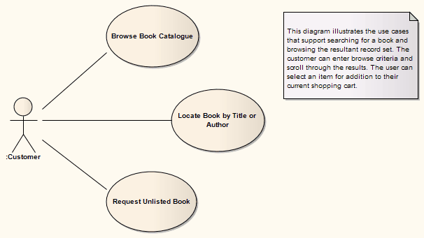
Example Diagram
The following diagram illustrates some features of Use Case diagrams:
Toolbox Elements and Connectors
Select Use Case diagram elements and connectors from the Use Case pages of the Toolbox.
Tip: |
Click on the following elements and connectors for more information. |
Use Case Diagram Elements |
Use Case Diagram Connectors |
|
|
|
|
|
|
|
|
|
|
|
|
|
|
|
|
Note: |
Invokes and Precedes relationships are defined by the Open Modeling Language (OML). They are stereotyped Dependency relationships; Invokes indicates that Use Case A, at some point, causes Use Case B to happen, whilst Precedes indicates that Use Case C must complete before Use Case D can begin. |