| Prev | Next |
Block Definition Diagrams
A Block defines a collection of features used to describe a system, subsystem, component or other engineering object of interest. These features can include both structural and behavioral features, such as properties, operations and receptions, that represent the state of the system and the behavior that the system might exhibit.
Getting Started with Blocks
A SysML Block Definition diagram is the starting point for describing your system structure. Using Blocks, you can model your system hierarchy and the relationships between systems and subsystems.
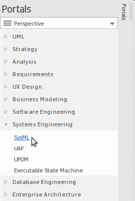
Setting the Perspective and Workspace
Systems Engineers who are experienced in using Enterprise Architect will generally select a Perspective from the Systems Engineering Perspective Set; typically this will be the SysML Perspective, giving them access to patterns and toolboxes tailored for creating SysML diagrams such as Block Definition and Internal Block diagrams.
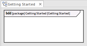
Create a Block Diagram
A Block diagram can be created within a selected Package using any of these options:
- The Browser window context menu (Right-click on a Package and choose 'Add Diagram')
- The Model Wizard ()
- The New Diagram dialog ()
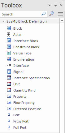
Creating a Block Element
Block elements can be created using the 'Add Element' option on a Package context menu, or by using the SysML Block Definition toolbox to place a Block on a Block Definition diagram (BDD).
It is common for Blocks to appear on multiple BDDs, where each diagram is designed to address the concerns of a particular stakeholder or stakeholder group.
Blocks are discrete modular units that provide the foundations for system description. A Block models a collection of features that are used to define an aspect of a system or the system itself.
Block features are of two fundamental types: structural features and behavioral features - what a Block consists of and what it does.
Structural features can be further categorized into three sub-types:
- Parts - that describe the composition of a Block; for example, a vehicle is composed of two axles and four wheel assemblies
- References - that describe the Block's relationship with other Blocks (including itself); for example, that a metropolitan train has a relationship to a station and to an overhead wiring system
- Values - that describe quantifiable aspects of a Block; for example, dimensions, temperature and luminosity
Behavioral features can be subdivided into two subtypes:
- Operations - typically representing synchronous requests
- Receptions - representing asynchronous requests
Block Relationships
A Block's relationships to itself, to other Blocks and to other types of element help to describe the structure of a system, subsystem or component.
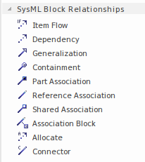
The core Relationships used in modeling Blocks include:
- Item Flow
- Generalization
- Part Association
- Association
- Association Block
Block Definition diagrams are often the starting point for creating other diagrams, such as Internal Block Definition diagrams, Parametric diagrams and Activity diagrams. Features that appear on the Block Definition diagram, such as Parts and Ports, typically form the basis for modeling in these other diagrams. Enterprise Architect's Synchronize Structural Elements feature can be used to populate Internal Block diagrams and Parametric diagrams using information from your Block Definition diagram.