Show Posts

This section allows you to view all posts made by this member. Note that you can only see posts made in areas you currently have access to.


Messages - davisford

Pages: [1] 2 3 ... 5
1
General Board / Re: How to elide superclass property membership?
« on: August 04, 2008, 08:00:31 pm »
Hi, I looked into this further, and I still can't figure out a way to do this, so I'm bumping this message up to see if anyone has any other ideas.

I want to elide the superclass qualifier on attributes that are inherited when showing the subclass.

For example, Parent class has attribute called "foo" and Child class has attribute called "bar".

When I show Child class I see this in attributes compartment:

Parent::
  foo : int
bar : int

I want to get rid of the Parent:: qualifier.  I tried several things in Feature Visibility dialog to no avail.

I looked into creating a custom ShapeScript to do this, but had no luck.

Does anyone have any clue if this can be done?

FYI: the reason for desiring this behavior is that the UML in question is a specification, and the published specification has different audiences.  Some audiences will not care about this superclass relationship, and it will only cause confusion when reading the spec..but we need to maintain this relationship for modeling/software purposes.

TIA

2
General Board / EA on Linux - no Tricks!
« on: November 05, 2007, 05:21:54 pm »
Howday,

Recently have moved my dev. environment from Mac OS X to Ubuntu Linux.  Ubuntu is really starting to shine as a desktop-replacement, dev-env.  Anyhow, I use EA as a modeling tool often.  I'm happy to report that it works out of the box with the latest Wine w/o all the convoluted steps and additional software packages you need to purchase -- listed on the EA guide to installing on linux.

There are some set-backs -- it is slower, and a little clunkier, but it seems to work fine.   I didn't do anything special to get it to work.

I installed wine with apt-get.  I ran the EA .exe installer.  First time, all I saw was splash screen.  After a reboot, I tried again, and the app came up, created a new model, made some new diagrams, saved it, etc.  Have not exercised it much, but this is pretty cool news.

Hope it helps somebody!

Regards,
Davis

3
General Board / Does EA Support XMI v2.1?
« on: April 11, 2007, 06:59:02 am »
Simple question.  Import/Export of XMI in EA seems to not support the latest XMI specifications, is this true?

We're writing models in XMI that we want to import into EA, and we need to know which version of XMI is supported.

Thx,
Davis

4
General Board / Re: Diagram Export
« on: January 24, 2007, 11:40:46 am »
actually simon, i found what i needed already.  i did not realize this until later, but including diagram on XMI export does include an images directory with each individual binary (in this case .emf form).  they are named by GUID, and i believe the GUID is also referenced in the XMI, so it is easy to link them up.

this is precisely the functionality i was after.

5
General Board / Diagram Export
« on: January 23, 2007, 06:05:35 pm »
Hi, what are the options for diagram export.  I know you can do CTRL-T and save a diagram in various formats.  I know you can generate a digram-only RTF file that includes all the diagrams embedded in the RTF.

I know you can export to XMI and include diagrams, but it seems this only writes out the XML that references the other XMI elements -- it does not embed the actual binary into the XML.  Is there a way to do this?  If I could do this, it would actually provide exactly what I want.

The end goal -- for a specification system -- the desire is to capture all the diagrams out of an EA model as EMF or WMF format.  These diagrams want to find their way into a FrameMaker-driven publishing system.  Currently, I'm guessing what we'd have to do is export the diagram-only RTF, and manually copy out each diagram, store this in the specification repository, etc....blah.   Looking for a much better way..is there one?

Thx,
Davis

6
General Board / Specification Publishing System
« on: January 23, 2007, 10:10:03 am »
Hi, I have a general question / problem to solve here, and thought I'd post it to the group, and see if anyone has any pointers / ideas.

We have a global specifications team that creates product specifications for the products this company sells.  Some of these specs are created in UML using EA...a lot of the rest may be just general text, drawings, etc.  

Currently they use Framemaker as the major tool to generate the specs.

We want to have a central repository for all specification material, and the format to store it in should be XML. This will likely be an XML database.

For EA then, we can export the UML as XMI and also store this in the XML database.

I'm not really familiar with FrameMaker or its capabilities, but I am to understand that one can use plugins to generate PDFs with variable content by pointing it to such a database.

I'm not sure how it would or would not deal with the XMI portion.  I'm guessing that some XSLT could be written to transform the XML into whatever Framemaker expects?

Has anyone had extensive experience with these technologies, and could provide some commentary?  Is anyone doing something similar?

There is the option to use EA for all specification material, but this is not feasible.  EA generates decent UML-driven documents, but the UI is not suitable for all of the spec content needed here.  Therefore, we'll only use it for the UML-driven content of the specifications.

Regards,
Davis

7
General Board / Re: OCL in v6.1 Build 792
« on: August 02, 2006, 10:51:22 am »
Ok, here's another really, really trivial example:

Create a class diagram.  Add a new class => Class1.

Add an Attribute called "someNumber" of type int to Class1.

Add a Constraint to Class1 of type OCL.

Name the constraint "minNumber" and add the OCL code:

Code: [Select]

inv minNumber: someNumber >= 5


Save -> OCL Validation Successful.

Now select Class1 on the class diagram, and do CTRL+ALT+V for model validation.  

You will get a warning that the OCL invariant is violated -- why?  I don't know.

Now try this:  

Open the properties page for the attribute someNumber, and fill in the initial value as '6'.

Now re-run the model validation.  It still fails.  Intuitively, the only guess I had as to why the OCL invariant was violated was b/c there was no initial value to compare against -- but this is not the case.

Any clues?

8
General Board / OCL in v6.1 Build 792
« on: August 02, 2006, 10:39:16 am »
Hi - we are interested in applying OCL in some UML models that serve the pupose of specification.  Therefore, more formality is better.  Henceforth, OCL would be nice to apply here.  

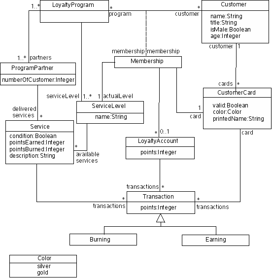
To get started, I grabbed a copy of http://www.amazon.com/gp/product/0321179366/ and I re-created the sample class model in the book for the "Royal & Loyal" example (Chapter 2).  The class diagram looks like this:

-- taken from this website: http://maude.sip.ucm.es/itp/ocl/examples.html

I re-drew this in EA as a class diagram, and tried adding my own OCL constraints to it, and then doing model validation.

For example, I added this OCL constraint:

Code: [Select]

context LoyaltyProgram
inv minServices: partners.deliveredServices->size() >= 1


However, in EA, you do this by opening the Properties page of the LoyaltyProgram class, hitting the Constraints tab...then adding a new Constraint of Type OCL.  In the Constraint box, I typed the name
Code: [Select]
minServices, and in the box that follows I typed:

Code: [Select]

inv minServices: partners.deliveredServices->size() >= 1


You don't need to have the

Code: [Select]

context LoyaltyProgram


part because this is implied via the GUI.  In fact if you add the context part, it fails OCL validation.

So, when I hit Save, a box pops up and tells me "OCL validation Successful" -- seemingly indicating to me that the OCL syntax is correct.

However, if I select the LoyaltyProgram class, and do CTRL+ALT+V (do model validation on this element), it reports to me:

Code: [Select]

MVR040001 - warning (LoyaltyProgram (Class)): OCL violation: inv minServices: partners.deliveredServices->size() >= 1


So, it is giving me a warning that this is in violation of the constraint.  Two things I don't understand here:

1. Why is this in violation?
2. If it is in violation (which I don't believe it is), why is this a warning and not an error?


9
General Board / Re: Deployment diagram: node instance attributes
« on: August 02, 2006, 05:12:28 pm »
Hi Simon, when I referred to the images...I meant there seems to be a deployment diagram maybe one or two packages up in the example that has more "visio-like" graphics...

I was wondering how this was done?  I tend to make deployment diagrams often, but the audience can be picky.  Engineer-types can appreciate it, but more mgmt types really like the kiddie-graphics. :)

10
General Board / Re: Deployment diagram: node instance attributes
« on: August 02, 2006, 12:21:18 pm »
Hi I took a peek.  Those are attributes of the Classifier type that that guy is a type of on the diagram, but I'll be honest and say, I can't figure out where he entered that info in.

Another question I have is how / where he got all the very nice graphics for the deployment diagram?  This makes much nicer viewing for exec types than UML box nodes.

11
General Board / Re: Deployment diagram: node instance attributes
« on: August 02, 2006, 11:45:44 am »
Hi - I did not look at the EA example diagram, but I typically do this with tagged values.

This can be modeled different ways in UML, but I find the easiest thing to do is use tagged values.

Here is how to do this in EA:

View -> Tagged Values (or CTRL+SHIFT+6)

Select a Node on a deployment diagram.  Go to the tagged values property window and press the New Tag button.

Enter a name/value pair for the tag.  For example:

Name = Memory
Value = 2048 MB SDRAM

To display tagged values on the diagram then, right click somewhere in the Diagram and bring up the Properties.  Tick the "Show Tags" box.

Voila.

12
General Board / Re: RTF Document Generation
« on: May 27, 2005, 05:14:37 pm »
I find the new WYSIWYG document template editor to be really an outstanding step toward creating perfect documentation with the tool.  

It takes a bit of getting used to, but it is pretty powerful.

My only major gripe thus far is that in the Sections window, you cannot repeat elements.  For example, if I wanted to re-use a package.name in various places in the document, I cannot -- I have to use it only in one place.  It would be very useful to simply drag-n-drop references (GUID) from the model into the WYSIWYG editor.  If the model changes, it is automagically updated in the documentation that is generated.  

13
General Board / Re: Oracle / DDL / EA / etc.
« on: May 08, 2006, 08:58:45 pm »
Quote
Hi Davis,

I think you have got representations of instances of a metamodel - the instructions - as well as instances of entities within the metamodel. Looks a bit weird when I write it down, but makes perfect sense.


David/Thomas - thx for the insight.

You hit the nail on the head above.  Let me try a concrete example:

The data dictionary describes things such as a Point Feature, and a Point Feature can have Attributes, and Attributes can have name/value, etc.  That's really simplifying the model, but it will work as an example.

The data dictionary schema describes all that from a conceptual point of view.

In the real data for the data dictionary you have point of interest (POI), and you can have many such as:

Zoo
Restaurant
Cafe
etc..

So, in EA, I can reverse engineer the data dictionary schema into one or more class diagrams that describe the "metamodel".

What I want to do, is find some way to also reverse-engineer the real data into class diagrams and make sure it conforms to the schema.  

Following the concrete example, this means I could have a class diagram that shows multiple POI's such as Zoo, Restaurant, etc.

The goal is visual representation of the meta-model and the data.

Consumers of the meta-model/schema will be spec maintainers who tweak the meta-model as they update the spec.

Consumers of the visual data will be people that want to browse the contents of the dicitionary to see what's in there and have editing capability.  For instance, they may want to add a new POI like police station.   This should be as easy as adding a new class and synching with the database.

After that explanation, do you guys have any insight/clues on what could be done?

I'll follow up on the links you sent, David.

Thx,
Davis

14
General Board / Oracle / DDL / EA / etc.
« on: May 07, 2006, 04:48:25 pm »
Hi, I have sort of a general problem, and thought I would post here to look for solution ideas.

Quick background: working in Geographic Information Systems domain.  We're using Oracle.  Oracle stores primitive map data (i.e. points, lines, polygons, etc.) in one database.  Another database (we call data dictionary) defines a conceptual model on how to compose geometric features from primitive data -- for example it describes how to make roads out of lines and counties or countries out of polygons.

I can use EA to import the data dictionary schema into a class diagram, and this is very handy.

I would like some way to also import the actual data in the data dictionary database into EA.  

Since I can import the schema into EA, and then forward engineer an XML schema (XSD)...I guess what I'm looking for is a transformation or mapping from XML (that conforms to the XSD) to UML (class diagram).

The actual data is not that large, but a visual model of it is the real "end" goal here.  We can already get a logical visual model of the schema via EA import through ODBC.

I'm just guessing at ways to do this...but I'm sure other people have considered this problem before.  Any ideas or suggestions?

Regards,
Davis

15
General Board / Re: Control Flows on Activity Diagrams?
« on: March 21, 2006, 07:43:23 am »
Hi Jim, I have to disagree.  The fact that the tool may/may not enforce the drawing of one line that looks the same as another between two elements is not visually distinguishable for me, and provides no concrete semantics when reading the diagram.  This problem is exacerbated by the fact that activities and actions are dangerously close to looking the same.  Last time I tried to use this in EA, the object port/node did not automatically fill in; my question was more specific to that scenario.  Even in the case that you're modeling formal petri nets, if the arrows provide no visual distinction, just the fact that an arrow goes from/to an object defines it as an object flow, and if it is to/from an activity to another activity, you have no way to know...well, now it appears you do with the object node/port.  I still find it dangerously ambiguous and only those that are very familiar with the model syntax/semantics will get it.  In my humble opinion, I find it a poorly defined part of the UML spec.

Pages: [1] 2 3 ... 5