Book a Demo

Show Posts

This section allows you to view all posts made by this member. Note that you can only see posts made in areas you currently have access to.


Messages - pauldab

Pages: [1]
1
General Board / Re: MBSE Process
« on: June 17, 2022, 08:24:47 pm »
    Hi Takeshi,

    Thanks for the reply.
  • First, I create context diagrams to define each context e.g., who are related to the system and what are outer systems.

So you create directly part properties on those diagrams for Power Control System and other systems?
Then you connect them with connectors and maybe show items flows?

  • Then, find Requirements in each context.
  • And I also find Usecases in each context.

Makes sense. In my approach I am trying to use context blocks and then trace all necessary requirements and use cases to this block.

  • I will not create context block like you. To describe structures for each context, I will create a BDD and a IBD for each context. In BDDs, Blocks are commonly used (i.e., copy some Blocks in a main BDD by Ctrl+C and paste them onto a context BDD by Ctrl+V). If I want to describe IBD for each context, I will create IBDs under the main Block (in above image, the Power Control System block)


To summarize, I will use diagrams to describe contexts but elements (in this example, Blocks and Actors) in diagrams are commonly used (except Properties in this case - Properties are instanced objects of Blocks).


I assume that IBDs in Context Diagrams show connections of our Power Control System with external systems, and IBDs under Power Control System show internal connections.

Best,
Paweł

2
General Board / MBSE Process
« on: June 15, 2022, 07:35:42 am »
Hi,

This topic is somewhat related to my previous one: https://sparxsystems.com/forums/smf/index.php/topic,46948.0.html  (Logical & Physical System Design in SysML and Sparx), but I would like to extened it and discuss additional modeling concepts for the system and whole MBSE.

As a initial starting point I have found and would like to spread the Minimum MBSE process introduced and proposed by Sparx JAPAN:

https://www.sparxsystems.jp/en/trace/minimumMBSE.htm
https://www.sparxsystems.jp/en/trace/MinimumMBSE.pdf

This is simple, yet contains the most important concepts (without specialty engineering e.g., SWaP-C, FMEA, Reliability, Availability - but surely could be extened with those).

My proposal to MinimumMBSE would be to introduce multiple system contexts:

I am considering multipile system contexts (i.e. operational context, maintenance context, production context).
So every system context can have at least one UseCase, but can have more.

And after applying proper SysML I get couple of part properties representing my system (in this case Power Control System):

So far I have thought that this is smth inherently bad, but...

... after I named those part properties It perhaps makes more sense. But still my block definition directly won't have any connections to other systems by itself.

1. So my first question is what do you think about that approach to system design in different contexts with couple part properties (different views?) and how to generate any specification out of that?

2. Let's, for the sake of discussion, that we are at physical level. After finding my two connections (mechanical and electrical) in production context I could then manually add two ports to represent those interfaces on system side:

and then use those on my production context part property.

Then simply also include those ports in my production context ibd and "rewire" the connectors form part poperty to specific ports:


This way system definition with those ports could be passed, with additional requirements (that could be traced to the port) to detailed design for specification (mechanical connector selection, wires diameter etc).

Are there any better alternatives? Ideas?

3. Can a part property exhibit state the same way as instance specification?

Because if we were to use in the system design instance specifications (representation of built system) we could define:

and this would allow to make the model more complete, so states could be used included in system specification:


So far I wasn't able to find a way in Sparx to add states to part properties (also a representation of my built system?).

Best regards,
Paweł

3
Thanks,

Paweł

4
Hi Takeshi,

Thanks for the reply.

Suppose we create a IBD which contains two Properties typed by Blocks and connected them by a Connector and create an Activity diagram which contains two Partitions typed by the Blocks. Each Partition has an Action, and they are connected by a Control Flow. I think this situation is okay, consistent.

Usually there are two or more Activity diagrams. I recommend creating Activity diagrams for each Use Cases. (i.e., Activity diagrams are used for describing Use Case scenarios and clarify which Actions each Block has. (Actions owned by a Block are its feature and/or responsibility.)

In this assumption, it is consistent that at least one of Activity diagram has a Control Flow between Actions on Partitions. If there is a Connector between Properties typed by Blocks but there is no Control Flow between Actions on Partitions typed by the Blocks in all Activity diagrams, it is inconsistent. I hope you agree this rule.
a.   I agree, but up to this point I was considering Object Flows instead of Control Flows. In general systems, system elements can exchange items – material, energy and data (information) and I would assosciate them with Object Flows. Those item flows are sent through the connector. So above description makes absolute sense for me if we were using Object Flows instead.
b.   I am not sure how to get physical with Control Flows – in Activity diagrams we are talking about tokens, but they are purely abstract. In real systems I suppose that we „implement” Control Flow by using Object Flows and sending some sort of item i.e. command (i.e. implemented by a signal or block).
I would say that in initial analysis we could use Control Flows, but then still they would have to be replaced with Object Flows?
c.   What about connectors that simply mean mechanical connection? Maybe we should tag those connectors as mechanical and exclude them from the above rule?

We sometimes do a trade-off analysis by using SysML models. In this analysis, there are two (or more) group of Activity diagrams, and we will choose best group to meet requirements. (Now I do not consider BDDs and IBDs. I know we might need to create groups of BDD and IBD for trade-off analyses.)
In this situation, if one of the groups has a Control Flow but another does not have, it is inconsistent for the latter group. But if we check for entire model, it is consistent because there IS an Activity diagram which has a Control Flow between Blocks. So, we need to define groups and check for each group. I want to say here that sometimes we cannot check entire model to confirm if it is consistent or not.
Ok makes sense. This is a matter of querying the model and being able to detect such occurrences.
How do you make such groups in SysML?
In another situation, suppose an artificial satellite. Usually there are two groups, one is common and basic features for satellites (the satellite bus. e.g., the Attitude Orbit Control System, AOCS) and another is mission-specific features (e.g., surface temperature monitoring). In model, we sometimes describe only mission-specific features because the satellite bus is already fixed and we can re-use. In this situation, if there is no Control Flow in Activity diagrams, it might be okay because it might be used in the bus. I want to say here that if there is no Control Flow or Connector and there is inconsistency, it might be okay for entire design.
This basically means that we should check automatically interfaces for your suggested consistency rule. Still if we are re-using I believe that we should add interfaces (connector and related item flow and performance and timing) between our new model elements and re-used blocks.
Anyway, we need to consider various things. This is why I consider it is difficult to create the checker by using the Automation Interface. Synchronizing is more difficult; we cannot determine automatically to synchronize to which model or diagram.
I am starting to realize that. I suppose that this is a true know-how of MBSE – how to find a sweet spot between details, synchronization and verification of the model. It seems like a daunting task.
Hope this helps,
 
So far our discussion helped me a lot  :) - thanks. I hope that it also will help other readers as well.

5
Gentlemen,

Thank you very much for the replies and your insight. Please find my additional comments below:

Regarding the parts you're getting under each system context block, this is normal behaviour. When you create a composition between 2 blocks, a matching part is created under the parent block with the role name + multiplicity. For instance if you create 2 composition links from System context 1 to Equipment 1 logical and give them different role names, you'll get the matching parts, named after the given role.
I agree – this is normal behavior and I understand it.
Note it is important to leave these parts under the main block and create your IBDs under this main block.
In general I agree also with that. If I design a real piece of equipment that has internal parts like PCB boards, cables etc. this makes great sense.

In my example I was showing a system context which, as I believe, is an abstract concept. Context can contain specific actors, external systems (as in my example above) and system may offer different functionality for actors in this specific context (generally goals to achieve).

So I want to use a power of modeling tool and be able to analyse those contexts separetly. If I stay „compliant” with above I finish with many instances (parts) which are not related (in a model). There is no traceability between those. So far this is my understanding.

So creating one system/component part and use it in every context gives me the whole system and it’s interconnections.

After writing all above I am wondering that not all connections and interactions may be used at the same time, i.e. in maintenance there is a connection (through cable) to test equpiment. So I am wondering now how to relate my system instance in different states to different connections.

Again different parts for every context could allow for that…. (showing different connections).

But how to correlate everything then in my final system spec?

Paweł
So physical elements can inherit logical elements operations.
The main issue with this is that in Sparx I cannot trace between relationships.
If you are arguing that physical elements are instances of logical elements, I do like the sound of your first option. You are correct, there is no relationship to depict an instantiation, to my knowledge this is the case with all modelling languages I am familiar with (and, in my opinion, it is a weakness of modelling languages.

I had couple of discussions about that. It's very much a matter of taste - it can take hours to discuss such topics.
Right now after Takeshi posts I agree that one must consider "IS-A" relantionship. In my example that makes sense, but more generally as I have thought about it you may have functional blocks, like "Security functions", "Time Management", "Communication Module", etc. Then you cannot use "IS-A" relationship when you go to the physical level - it makes sens to allocate those functional components to physical component.

The last question about consistency between IBDs and Activities, yes, we can check by using the Automation Interface. If two Actions are connected by a Control Flow, and each Action is on a Partition typed by a Block, and an Association connects two Blocks in a BDD or two Properties of the Blocks are connected by a Connector in an IBD, is it okay? Basically yes, but I do not know if this condition is ALWAYS correct.
Thanks I will look into it. What do you mean if this is always correct? Shouldn’t it be correct to make the model complete? Perhaps we could check that it’s not the case and use this information to fix the model/system spec?


6
Hi Takeshi,

Thanks for the reply and your opinions.

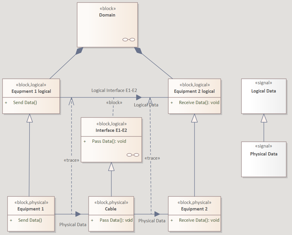
- Usually we do not describe connections (interactions) between sub blocks in the BDD. They should be described in IBD (of parent Block). In your example, 'Logical Interface E1-E2' should be described in the IBD of Domain block.

Thanks. I believe that it is possible in general - so we can create associations between blocks on BDD, and then type the connectors on IBD with those associations (i.e. multiplicity). So far I was not able to find a good reason to this, so in general thanks for the suggestions - it may make my work easier.

This also leads me to another example:


So creating two context blocks IBD (but context I mean that our system communicates with different external equpiments in the same time, so it will have two connector, but let's say that I want to analyze those contexts seprately). So this has created two properties and I belive that this is wrong.

I general I create properties like that:


And then use those properties as my final system components and add specific connectors on System context 1 and 2 IBDs.

Please let me know what you think.

Also for the document generation purposes should I move the IBDs outside of System Context 1 and 2?

- I think tracing connectors is one of 'traps' in creating models. Everyone who wants to build/maintain 'complete' traceability, he/she wants to trace them. But costs of maintain them is not small, but in my opinion, to keep consistency and find impact when changing it is enough to create traceability among elements only.

Thanks I'll consider that.

- 3a: In your logical model, an Activity (and an Activity diagram) should be owned by the Domain block and sub blocks (e.g. Equipment 1 logical) should be shown as an Activity Partition in the Activity diagram. Each sub block has not Activity but Actions. It is okay that you define operations and drop them as CallOperationActions in the Activity diagram.  But I do not do so because the information will be duplicated (operation and its CallOperationActions). For me, I do not define any operations but define as Actions because I just want to know 'What to do' for each Blocks, not want to create a perfect model.

So in my above example my systems contexts can own the Acitivities and the specific activities will contain CallBehaviorActions.
So In general I could put those activities anywhere I like, but I suppose that it helps to organize the model?

-3b: Generalization should be used for the items in the same 'world'. In this case, usually we use Allocations. This means that each Logical Block is allocated to one or more Physical Blocks.

Thanks, makes sense.

-3c: If I understand correctly, there is no way to synchronize (or check consistency) between Flows in Activity diagrams and Connectors in IBDs by using EA.

I was wondering if it could be achievied by using scirpts and underlying model schema.

Best regards,
Paweł

7
General Board / Logical & Physical System Design in SysML and Sparx
« on: June 06, 2022, 04:04:46 am »
Hi,

I am trying to model logical architecture and physical architecture in Sparx.

1. This is what I came up with so far:


So physical elements can inherit logical elements operations.
The main issue with this is that in Sparx I cannot trace between relationships.

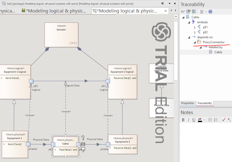
2. The other solution:


This is perhaps more preferable, because one could use full port and type it with a concerete connector. This physical port with a connector could be traced to multiple logical ports. Still one could trace physical elements like Cable to logical association - when you try to trace block it gives a ProxyConnector depedency.

Still in this case I am not sure that it's very compliant with SysML - connecting ports on bdd with connectors.
Also if one connects physical E1 with Cable with association, then you cannot type a connector on ibd between ports on those element propreties...

3. Wondering if:
a) it's better to use operations or maybe allocate activities to block elements.
b) to use generalization from physical components or realisation or any other relation.
c) how to relate connectors to object flow (the same issue with relationship tracing)

I would be grateful for any insights or suggestions.

Here you can download the qea file:
https://drive.google.com/file/d/1f_jok4iCn1n30aHJm9eheouwcq2mYDnJ/view?usp=sharing

Best regards,
Paweł

Pages: [1]