Book a Demo

Show Posts

This section allows you to view all posts made by this member. Note that you can only see posts made in areas you currently have access to.


Messages - Takeshi K

Pages: [1] 2 3 ... 42
1
Hi Guillaume,

If I understand correctly, the third (3rd) and fourth (4th) parameters are relative position values.
But it is tricky to determine actual position to draw a subshape.

The important point is that the calculation of the reference point used for relative values is a bit cumbersome.

In this case, the layouttype is default, this is may be 'TopDown'. In the 'TopDown' type, the 3rd parameter is simple, just relative value from 0. If the 3rd value is -50, the subshape will be drawn 50 point left from the rectangle by the drawnativeshape command. After adding a subshape the reference point will be moved to lower (in the 'TopDown' type). In this case, the second parameter (height) is 50, so the reference point will be 50 (0+50). The Y position for the next subshape will be calculated from 50.

We can understand this behaviour by trying the following script. (and change 4th parameter of the second addsubshape)

addsubshape("test", 50, 50, -50, -50); //1
addsubshape("test", 50, 50, -50,  0); //2

Before the first addsubshape, the reference point is (0, 0), this is default.
By the first addsubshape, the reference point will be (0, 50) because the height (the 2nd parameter of the first addsubshape) is 50.
So, the second addsubshape will be drawn from (-50, 50) - in the 'TopDown' type, the 3rd parameter is just relative point from 0, the 4th parameter is calculated from the current reference point - 50 (the 2nd parameter of the first addsubshape) + 0 (the 4th parameter of the second addsubshape)

It is similar when the layouttype is LeftRight, the X position is relative.

This seems very tricky, but because of this behaviour, we can draw subshapes nicely without 3rd and 4th parameters (addsubshape of 2 parameters is commonly used).

HTH,


2
But Copilot throws an issue:
' Sorry, your request failed. Please try again.
Copilot Request id: 37d72ba4-1757-43e8-becc-6763ef90ff8d
GH Request Id: 647D:3E781C:528352:5B6037:696F8921
Reason: Request Failed: 400 {"error" : {"message": "missing required Copilot-Vision-Request header for Vision requests","code" :""}} '

This error seems that there was an error between Copilot and GitHub (GH). My add-in never returns an error or requests the Copilot-Vision-Request header. This error maybe relates to Copilot Vision feature, so I cannot help you.

3
The 'Composite Diagrams' and 'Composite Structure Diagrams' are terms in the context menu. I don't understand exactly what these terms refer to.

But my current implementation of the MCP is 'owned diagrams', not 'Composite Diagrams' nor 'Composite Structure Diagrams', nor linked diagram. And this 'owned' means that diagrams under the target element in the Browser.

I think that there could be an option to add 'linked diagram' or 'related diagram' to return the  'Composite Diagrams' in the menu item. Anyway, the linked diagram (i.e., the  'Composite Diagrams' in the menu item) is not owned, so I think it is not correct to include the diagram to 'owned diagrams'. Please wait the next release:-)

4
Hi Takeshi, the command seems to have a bug. 'get_element_information' always returns 'empty' for 'Owned Diagrams'. Goal is to find out the composite diagram / child diagram of elements.

Hi Viking,
I have checked the above issue, but I cannot reproduce it. This means that the MCP returns child diagrams when you create a diagram by 'New Child Diagram' | 'Composite Structure Diagram' from the context menu, or when you add or move a diagram in the Browser window.

However, if you 'link' a diagram from the 'New Child Diagram' |  'Select Composite Diagram' context menu option, the linked diagram is not included in the 'Owned Diagrams' information because it is not owned by an element, just linked.

If you can easily reproduce the issue with the newly created project file, please send me the file. ([email protected])

5
Hi Geert,

Thank you so much for your comment. Your comments are very welcome and I agree some of your comments.

About the following points, maybe we can solve by requesting AI to do so.
- all elements the same size
- elements as the same horizontal/vertical level
- elements the same distance from each other
- link pools/Lanes with the proper elements (e.g. PartnerRole etc...)
My addin already has the interface for those.

About the connector style and routing, currently we cannot specify them. Especially latter, maybe you know, this is not easy to route nicely in the current EA API/storing data format...


I think it's important to consider how we use AI/LLM in our business/work. I once heard someone say that if we want 100% quality, we shouldn't use AI. If we think we can skip 80% of our work with AI, AI is our friend.

For example, if we want, we can create hundreds of BPMN diagrams from very large Word documents by asking AI to generate diagrams and then waiting for it to finish. Of course, we would still need to manipulate layouts and correct AI misunderstandings, but I think this is easier and faster than creating all the BPMN diagrams manually one by one. In Enterprise Architect in particular, adding pools, changing their size, adding lanes inside pools (which then requires us to change the size of the pools again), adding BPMN elements, connecting them and layouting them beautifully are very tedious work.

However, someone (e.g. one of my colleagues - he never use AI) might argue that many low-quality artifacts are worse, and that creating them manually results in a higher quality product (and we can save time, compared to 'fix' AI generated artifacts.) Yes, that is also correct. The most important thing, I think, is how, where and when we use AI.

6
Hi Viking and all who are interested in auto-generation by AI,

Regard to the following Viking comment, now the latest MCP server can generate better BPMN diagrams including Pools, Lanes, better layout, etc.

"I haven't tested your workaround solution for BPMN yet, but I will definitely do so.". Here are finally my test results:
  • The sterotypes are used and displayed for all elements I was using: events (!), activities, gateways.
  • As part of the prompt I said which task types to use, but I got only 'abstractTasks'. I will futher investigate this issue.
  • mcp created lanes for each involved role. But it arranged them as a row (not on top of each other), And it did not put the respective activities into the lanes. Instead Copilot says: "The fundamental issue: The MCP server's createelement and setelementproperty commands don't seem to support proper BPMN lane Containment. This is similar to the limitation we found with UML attributes - the MCP Server (v2.1.0.0) doesn't expose all the necessary commands for complete BPMN diagram modeling."
  • The layout is quite good. But it is vertical and cannot be changed. BPMN diagrams are more horizonal and this should be the outcome, if the layout cannot be adapted.
  • The created diagram is not correct but my understanding is that mcp cannot help here (e.g., only diverging gateways have been created, but not converging ones).

Example request for your AI (LLM):
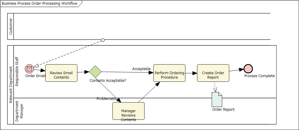
Please create the following process as BPMN diagram within the currently selected package.

1. When an order email arrives from a customer, the responsible staff member in the relevant department reviews the email contents.
2. If the contents are acceptable, that staff member performs the ordering procedure.
3. If the contents are problematic, the department manager reviews the contents, after which the original staff member performs the ordering procedure.
4. Once the ordering procedure is complete, create an order report and finalize the process.

Result:
(by Claude Desktop, free plan)


I have not modify anything including position and size. We need to use the prompt for BPMN which is offered by the MCP add-in.

Enjoy!


7
General Board / Re: Diagram Zoom level in HTML Report
« on: January 13, 2026, 10:18:18 am »
Changing the following value to 100% might ease your situation.

User Preference (Ctrl + F9) -> the Diagram group (left pane) -> Scale Saved Bitmaps to

HTH,

8
We can create elements and diagrams, and place existing elements onto them. As I mentioned in my last post, I split the tool into two for better performance and to support more situations. However, we usually do not need to specify which tool the agent should use to fulfil our requests, as the agent can automatically determine this.

Simply make your requests to the AI. The AI will generate the necessary packages, diagrams, elements and connectors, and then place the elements on the diagrams.

9
Yes, new elements will no longer be placed on diagrams for various reasons, mainly due to user requests and ideas on how to use this MCP, as well as to improve performance.

We can now place multiple elements at once using the place_element_on_diagram tool. I will update the add-in so that it can create two or more elements at once, saving on AI costs and improving performance.

10
The version 2.2.0 has been released. I found and fixed some issues during my tests, but there may still be others.

11
The implementation for adding/modifying attributes and operations (including parameters) has been completed, now I am testing if they work well. I needed to change some internal existing behaviour to support them, so I need to check all main features.

I think I can release the new installer today or tomorrow.

12
Hi Viking,

Thank you for checking the behaviour in BPMN model.
Unfortunately, creating beautiful diagrams with the Pools and Lanes with the current MCP server. The server must offer functions ('tools' in the MCP world) to specify the location of elements and connectors.

I will consider offering these functions, but not in the near future.

13
Yes, the implementation of attributes and operations is currently underway. However, it will take longer to be released.

14
Hi Viking,

Thank you for your comment.

- Notation and size in diagrams

Currently, it is not easy to offer the 'tools' (MCP methods) for them, but I have added a feature to support the Template Package in Enterprise Architect.
Could you update the MCP addin to the latest (version 2.1.0) and then create a Template Package in your model, and then add a Archimate Compornent with your faviorite style?

- Adding attributes

Currently the MCP addin does not offer a tool to add attributes. I will add the feature in the future.

- cardinalities

On the version 2.1.0, we can modify the Multiplicities of connectors. Does this solve your situation?

15
Hi Viking,

I will try to offer a prompt for ArchiMate 3, but could you try if the MCP add-in works for ArchiMate?

1. launch Enterprise Architect, create a new ArchiMate diagram and then leave it (keep open)
2. for your LLM, tell the rule like the following:

Quote
When we create an ArchiMate component in Enterprise Architect, its type is 'ArchiMate3::ArchiMate_ApplicationComponent'.

3. then ask to your LLM like:

Quote
Create a new ArchiMate component named 'Test' in the currently open diagram in Enterprise Architect.

Pages: [1] 2 3 ... 42