| Prev | Next |
Introducing Internal Block Diagrams
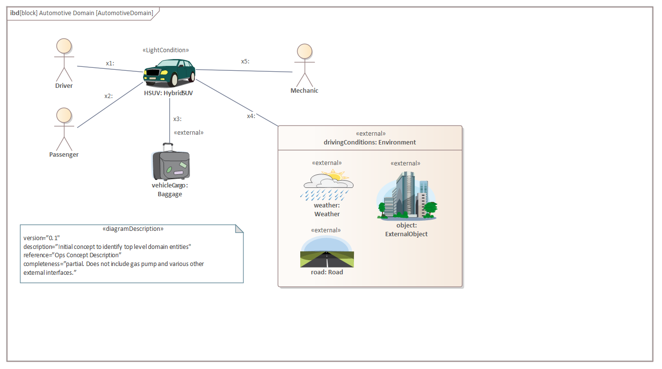
An Internal Block diagram provides a way of visualizing the internal structure of a Block, including its Properties and Parts and the way that these Parts relate to each other. The diagram is not required to display all the Parts that a given Block is composed of and it is common for an engineer to create a diagram that focuses on a particular aspect of a system or subsystem.
The frame of an Internal Block diagram represents the owning Block, so it will be named as such and the elements that appear on the diagram will be Parts that are instances of the Blocks that the owning Block is composed of. This Internal Block diagram shows an instance of a vehicle in a given context; it uses a number of images in place of the conventional SysML language symbols as a way of adding appeal and making the diagram more compelling to a non-engineering audience. For more information see the Internal Block Diagram Help topic.
Creating an Internal Block Diagram
An Internal Block diagram can be created from a number of places in the User Interface, such as:
- Design ribbon - Add Icon on the Diagram Panel
- Browser window toolbar - New Diagram icon
- Browser window context menu - Add Diagram
We will use the Design ribbon to create an Internal Block diagram. Firstly, select the location in the Browser window where you want the diagram to be located. In contrast to most other SysML diagrams the Internal Block diagram is typically inserted under its owning Block. Once the location has been selected in the Browser window, select the ribbon item:
Design > Diagram > Add

Selecting this option will open the New Diagram dialog, allowing you to name the diagram; the diagram name defaults to the name of the Block that contains the diagram. With the SysML perspective chosen and the version of SysML selected, a list of diagram types is displayed from which you select the Internal Block diagram. Click on the to create a new Internal Block diagram in the location selected in the Browser window. The diagram canvas will be opened, allowing you to start adding elements and connectors that describe the internal structure of the Block. Enterprise Architect will also display the 'Internal Block' page of the Toolbox, which contains the elements and relationships defined by the SysML specification to be applicable for constructing this diagram type. Any number of other Toolbox pages can be opened if required, in addition to the 'Common Elements' and 'Common Relationships' pages that are always available.