| Prev | Next |
Requirement Relationships
Enterprise Architect supports all the SysML Requirement relationships, which can be visualized in a number of different locations within the user interface, providing a flexible way of working with these important connectors. The relationships between elements (including Requirements) are not visible in the Browser window, as this would clutter the elements when there are more effective ways of viewing the connections.
The Relationships window is useful to have docked while viewing elements, either in the Browser window or in a diagram. As an element is selected in the Browser window or in a diagram, the context changes and the Relationships window will display just the relationships that exist between the selected element and other elements in the model, including other Requirements.
The relationships between Requirements and other elements, including other Requirements, can be visualized in any diagram including Requirements diagrams, in three different ways:
- A connector between two elements
- A compartment in the Requirement element
- A callout notation in the form of a note attached to either a Requirement or another model element
All three diagram notations have their purpose, and provide flexibility for the modeler to choose the appropriate representation for a particular purpose and audience.
The relationship drawn between two elements visible in a diagram is the most common way to visualize Requirement relationships; the dashed line is drawn from the client (the dependent element) to the supplier (the providing element). So in this example the 'Strip Illumination' Block is the client and it depends on the 'Low Light Visibility' Requirement, so the arrow points from the Block (client) to the Requirement (supplier).
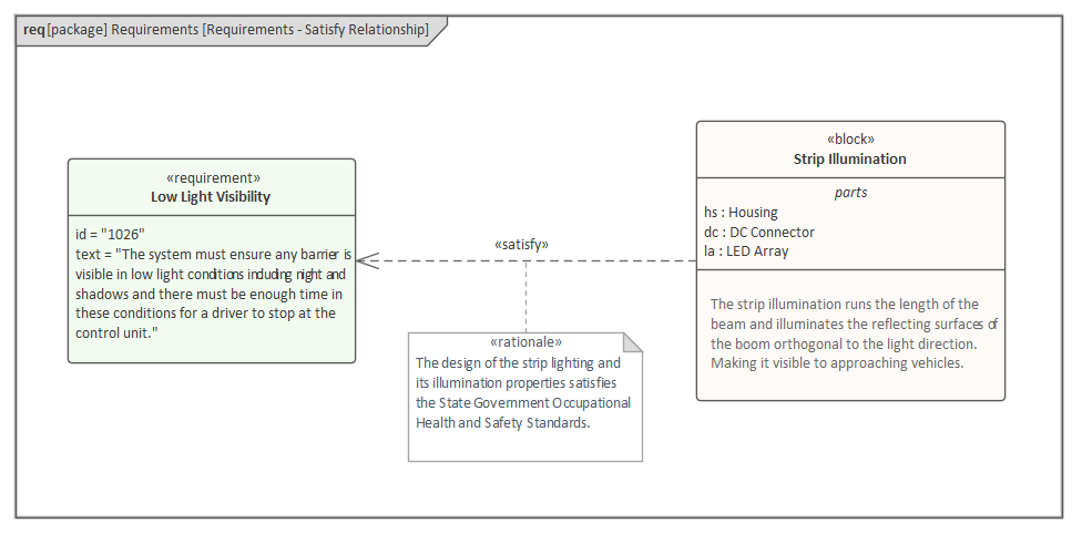
Notice also in this example that the modeler has chosen to display the Parts compartment, showing the Parts that make up the Block, and the Notes compartment that describes the Block. A rationale has also been added to qualify the 'Satisfy' relationship, and to provide an explanation as to why the Block was chosen in the context of standards.
Compartments can be used to display the relationships that a Requirement participates in, which is a compact and useful way of visualizing the Requirement relationships without the need to include the related elements in the diagram.
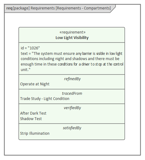
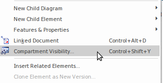
The list of visible compartments can be configured for each diagram element or for the entire diagram, providing fine granular control on how the relationships are visualized.
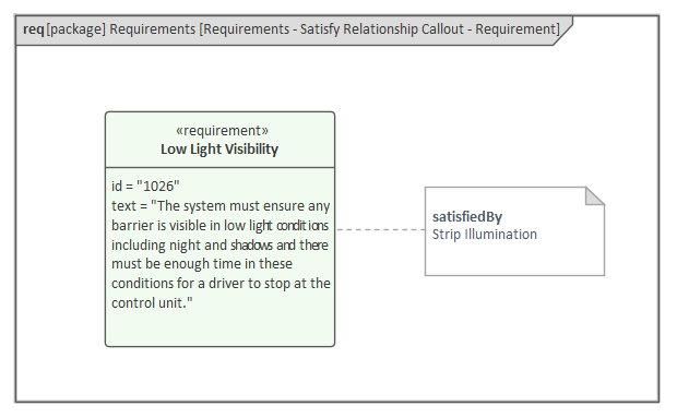
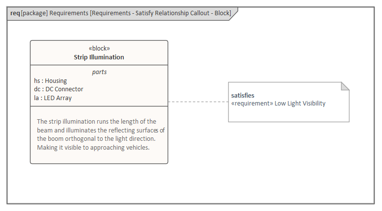
Alternatively, a Callout notation can be used to display the relationship in a note attached to either the Requirement element or the dependent element that the relationship relates to. This notation is particularly useful when elements appear in diagrams in which either the connector or compartment displays are not suitable, such as an Internal Block diagram, Sequence diagram or Use Case diagram, or in other diagrams as a modeler sees fit. The Requirement relationships are binary, meaning they have two ends: a supplier and a client. This means that the Callout can be attached to either a Requirement or the related model element which, depending on the relationship, could be a Block, Test Case, Use Case or other model element, including another Requirement.
In this diagram the modeler's focus is on the Requirement and the Block element is listed in the note stereotyped as <<satisfiedBy>>.
In this diagram, the modeler's focus has switched to a Block and the Requirement element is listed in the note stereotyped as <<satisfies>>.
The next section details the Requirement relationships, providing an example of each relationship.