| Prev | Next |
Creating Diagrams Elements and Relationships
Once a model structure has been set up and the application has been tailored to suit your needs, including the selection of the SysML Perspective and an appropriate workspace, you are ready to start creating elements and diagrams. While it is possible to create an element without first creating a diagram it is common practice to first create a diagram as a canvas for how the elements will be visualized. The first thing you will need to do is choose a location for the diagram in the Browser window. For example, you might be defining the fundamental architecture of your system and have defined a Package called 'Subsystems'. By selecting this Package you are telling Enterprise Architect that this is where you want a new Subsystems diagram inserted.
Creating a New Diagram
Enterprise Architect is a flexible tool and provides a number of ways of inserting a new diagram, including:
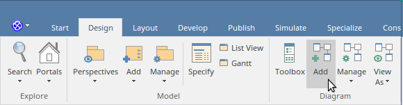
Selection from the Ribbons:
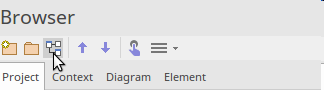
Selection from the Browser window header bar:
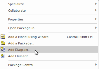
Selection from the context (right click) menu:
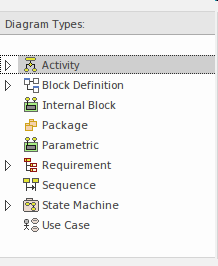
Regardless of the method you choose you will be able to select the SysML diagram type from the 'Diagram Types' panel of the 'New Diagram' dialog.
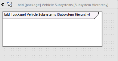
Let's continue on to create a Block Definition diagram to represent the Subsystem. Select the Block Definition diagram as the diagram type and enter an appropriate name. Once you click on the , a new (blank) BDD diagram will be created and the Block Definition Diagram Toolbox will be displayed ready for you, or a member of your team, to create elements and relationships.
Enterprise Architect will create a diagram canvas with a visible frame that represents the border of the diagram. The diagram frame is included because some users prefer to see it, but it can be hidden with no loss of meaning or compliance; once hidden the canvas then becomes the frame and the header information is contained at the top of the canvas. The frame can be included in saved or published diagrams by choosing this option in the 'Preferences' dialog.
Adding Elements to a Diagram
With the new diagram opened you are ready to start creating elements and relationships to describe the subsystems. There are essentially two types of Object that can be added to a diagram:
- New elements - Created by dragging an item from the Toolbox and dropping it onto the diagram canvas
- Existing elements - Placed on the diagram by drag-and-dropping an element from the Browser window
If you are starting a new project and have just set up your repository, you will not typically have elements in the Browser window so you will make more use of the first option and create elements from the Toolbox. As your project progresses it will become more common to use the second option and drag existing elements from the Browser window.
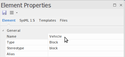
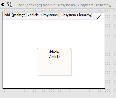
We will create a number of Blocks. Firstly we need a Block to represent the entire vehicle, so we will drag and drop a Block item from the Toolbox onto the diagram canvas. The tool will resize the frame to include the Block regardless of where you placed it on the canvas. The element will be given a default name of 'Block1'. Now using the Properties window, typically docked on the side of the diagram, change the element's name to 'Vehicle' by typing over the default name 'Block1'.
This will change the element's name in the Browser window and the diagram. Returning to the diagram you will see the newly added Block with the name 'Vehicle' enclosed in the diagram frame.
We could now use the same method to add a series of Blocks to represent each of the Subsystems.
Adding Relationships to a Diagram
Once you have added two or more elements you can connect them with relationships, which provide the semantic glue between the different elements in the model. For example, a Block element can connected to another Block element using an Part Association relationship. There are two primary ways that connectors can be added to a diagram:
- Quick Linker - an intuitive diagram device initiated by dragging a link between the Quick Linker arrow (at the top right of the element) and another diagram object
- ToolBox Items - connectors can be selected in the Toolbox and then dragged between two diagram objects.
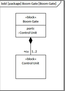
Either method will result in the specified connector being drawn between the two elements. Care needs to be exercised to ensure you are dragging in the right direction; the Part Association relationship, for example, should be dragged from the Block that is at the part end to the Block that is at the whole end. This will ensure that the little diamond marker at the end of the relationship is positioned at the correct end, indicating the whole-part relationship.
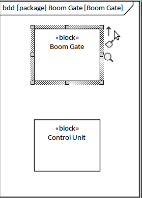
Regardless of the method that is used the result will be an Information Requirement relationship connecting the two Blocks. The direction and style of the connector can be altered, and any number of way-points can be added to route it differently as the model is developed. This diagram shows the added relationship where the modeler has also added a role name (+cu) and a multiplicity (1..2), indicating that a Boom Gate must have at least one control unit but could have as many as two. If a modeler were to inadvertently add the connector in the wrong direction it can be conveniently reversed by accessing options from the Advanced submenu of the connector's context menu.