| Prev | Next |
Custom Metamodel Diagram View
Enterprise Architect has a wide range of built-in diagram views, but you can also create your own Metamodels that define custom diagram Views. For example, you might define a specific Metamodel that addresses the needs of Requirements modeling in your organization, and then mandate that all Requirements diagrams use that diagram View instead of the built-in Requirement diagram Views. You can quickly add your diagram Views to the current model, where you or other modelers can apply them to your diagrams.
As an illustration, suppose you decide to make available a new SysML 1.4 Block Definition diagram View in your project, called 'MyView'. Users will access it through the 'New Diagram' dialog, expanding the Block Definition diagram type.
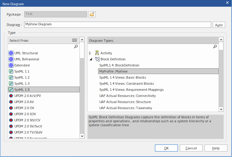
The fully extended name of the diagram View reflects the parent Profile name (MyProfile) and the View name (MyView) - hence 'MyProfile::MyView'. You could call the example View SysML 1.4 Views:: MyView to indicate that it is a member of the SysML 1.4 View suite.
If you are extending a UML base diagram type, with the Profile name 'UML', the equivalent View name could be something such as 'UML::Full Class'.
The users select the example diagram View to create a very simple SysML 1.4 Block diagram that can have:
- Two types of element:
- a SysML 1.4 Block element (an extended Class from the SysML 1.4 technology)
- a MyStereo element that you are defining within your new metamodel 'MyView' as a
Class with the stereotype MyStereo - One type of connector - a standard SysML Block Generalization (which is the same as a standard UML Generalization)
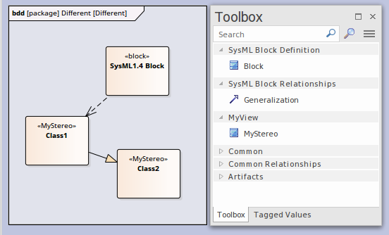
The diagram View makes the elements and connector available from the Toolbox, as shown, and from the Quick Linker.
The table Create Custom Diagram View in a Profile explains how to create a Metamodel that defines a new diagram View, finishing with the MyView example.
Access
|
Ribbon |
Design > Diagram > Toolbox: |
|
Keyboard Shortcuts |
: |
 > Profile > Metamodel
Create Custom Diagram View in a Profile
Operation |
Action |
See also |
|---|---|---|
|
Create the Profile diagram |
In your profile Package, create a new Package diagram and, in the Diagram Toolbox, open the 'Profile' page (select the 'Design > Diagram > Toolbox' ribbon option, then click on Drag the 'Profile' icon onto the diagram and give it the name 'MyProfile', selecting to add a child Class diagram of the name 'MyView', which you open. Expand the 'Metamodel' page in the Toolbox and note the:
|
Create a Profile Package |
|
Add View Specification |
Within a Profile, you use the 'View Specification' stereotyped element to identify the new custom diagram View as an extension of an existing built-in or stereotyped diagram. Drag the 'View Specification' icon onto the Profile diagram, and give the element a name; in our example, 'MyView'. The first thing to consider when defining a new View, is what diagram type or types it should be available for. The next two rows show how to define a View for a UML diagram and a Profile diagram. In both cases, click on the 'Extension' icon and drag from the View Specification to the diagram-type element, to create the Extension connector. |
|
|
Extending a UML Diagram Type |
To extend a base UML diagram type, drag the 'Class' icon from the Toolbox onto the diagram and, on the Properties window, give the element:
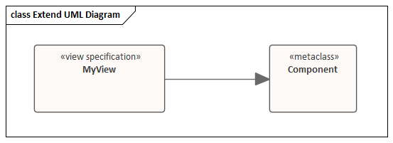
This example shows 'MyView' as previously created, extending the UML Component diagram.
The result is that in the 'New Diagram' dialog, an extra View is added under the UML Component Diagram type. |
Built-In Diagram Types |
|
Extending a Profiled Diagram Type |
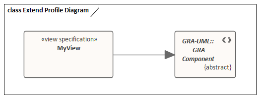
To extend a profiled diagram type, such as a BPMN or SysML diagram type, drag the 'Stereotype' icon onto the diagram and give the Stereotype element the exact fully qualified name of the diagram type. Because this is a reference to an external stereotype, it should also be marked as Abstract to prevent it being exported into the profile. To do that, display the Properties window, expand the 'Advanced' section and select the 'Abstract' checkbox. This example shows 'MyView' as previously created, extending the GRA-UML Component Diagram type.
The result is that the 'New Diagram' dialog will show the View we are defining under the GRA-UML component diagram. Note: If you do not know the fully qualified name of the diagram type you are extending, query the API to get the 'Metatype' field. In a JavaScript console you can use: ?GetCurrentDiagram().MetaType |
|
|
Exposing Objects in the Diagram View Toolbox |
An Exposes connector adds an object to the Toolbox page for the diagram View. For each element and connector to add to the diagram View's Toolbox page, you drag a 'definition element' onto the diagram and then click on the 'Exposes' icon in the Toolbox 'Profile' page and drag the cursor from the View Specification element to the 'definition element' to create the connector. The type of definition element depends on whether you are exposing a base UML element or a stereotyped element, as shown in the next two rows. |
|
|
Exposing UML Element Types |
If you are using base UML element or connectors in your custom diagram View, then for each element or connector:
For example: 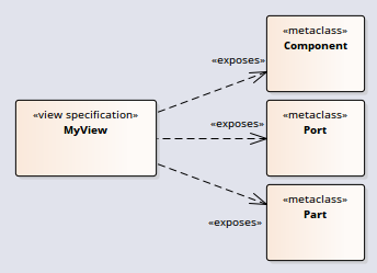
|
|
|
Exposing Profiled Element Types |
If you are defining a new stereotyped object in the diagram view, or using stereotyped elements already defined in other profiles, then for each element or connector:
For example: 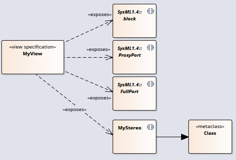
|
|
|
Completing the Example |
With reference to the earlier rows in the table, on the MyView Class diagram (the child of the MyProfile diagram):
This illustration represents the diagram that you have created: 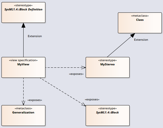 As you complete your diagram view, you might decide that elements of one type should be connected to elements of the same type or of other types by using specific kinds of connector. You would define this using Meta-Relationship connectors, as discussed in the Define Metamodel Constraints Help topic. Save the View Specification diagram. You can now can add it to an MDG Technology file as part of its parent Profile; you add the parent Profile to the 'MDG Technology Wizard - Profile files selection' page. See the Add a Profile Help topic. |
Define Metamodel Constraints Add a Profile |