| Prev | Next |
State Analyzer
The State Analyzer is a feature that can analyze, detect and record states for instances of a Class. The feature works by combining a state definition (defined on a Class as a constraint) and markers called State points. It is available for any languages supported by the Execution Analyzer, including Microsoft.NET, Mono, Java and native C++.
We begin by selecting a Class and composing our state definition.

We can get a picture of all the state definitions we've defined by placing the Class on a diagram and linking to the Class notes that themselves link to a particular state definition constraint. We explain how to do that in a later section.

State points are set by placing one or more markers in relevant source code.

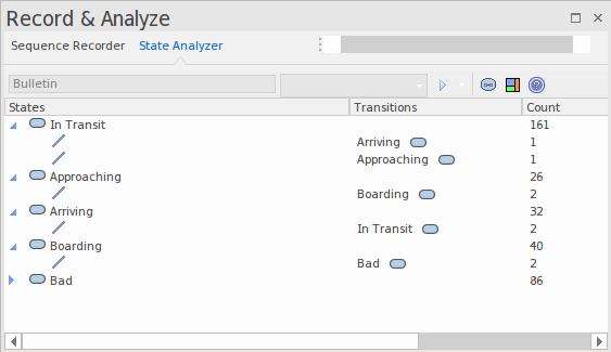
The program to be analyzed is run using the State Analyzer control. When the Execution Analyzer encounters any State point, the current instance of the Class is analyzed. Where the value domain of the instance matches the state definition, a state is recorded. Each time the instance varies, new states are thus detected. The control lists each state as it is discovered. Under each state the control lists the discrete set of transitions to other states made by instances of the class.

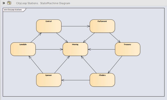
The information can be used to create a StateMachine.
Using the same information we can easily produce a Heat Map. This example shows a 'Train' Class, its 'Bulletin' State Definition (as a linked note), and the Heat Map it produced. The Figures in the map are percentages. From the map we can observe that trains were in the 'In Transit' state 46% of the time.

This is the analysis for the 'Bulletin' State Definition that produced our Heat Map.
Access
|
Ribbon |
Execute > Tools > Recorder > Open Recorder > State Analyzer Design > Element > Editors > Constraints |
State Definitions
State Definitions are composed in the Constraints properties of a Class element. The constraint type should be named StateDefinition.name, where 'name' is your choice of title for the definition. These titles are listed in the combo box of the State Analyzer whenever a Class is selected. You select a single definition from this combo box prior to running the program. The State Definition in our example is named 'StateDefinition.Location'. It defines states based on the location of instances of the CTrain Class.
State Definitions are composed of one or more specifications. Each state specification begins with the keyword 'statedef' which is then followed by one or more statements. Statements define the constraints that describe the state, and optionally a variable whose value can be used to name the state. Statements are enclosed in curly brackets and are terminated with a semi colon as shown:
statedef {
Location=0;
Departing.Name;
}
Naming states using variables
In this example, 'Location' is a constant and 'Departing.name' is a variable. An additional statement follows the constraints and instructs the name of the State to be assigned from the variable value. Here is the definition with the naming directive.
statedef {
Location=0;
Departing.Name;
}
name=Departing.Name;
Naming states using literals
In this example the State Definition only contains constants and the state is named using a literal.
statedef {
Location=100;
}
name='Central';
A single State Definition defining multiple State specifications.
statedef {
Passengers > 100;
}
name=Busy;
statedef {
Passengers >= 50;
}
name=Quiet;
statedef {
Passengers < 50;
}
name=Very Quiet;
statedef {
Passengers = 0;
}
name=Idle;
Default State
A State definition can specify a default 'catch all' state that will describe the state of an instance when no other state holds true. You define a default state for the definition with a statement resembling this:
statedef {
Location=0;
Departing.Name;
}
name=Departing.Name;
default=Moving;
In this example, while execution is in progress any instance detected having a non-zero 'Location' attribute will be recorded as being in the 'Moving' state.
You can choose to exclude the recording of the default state by disabling the 'Include default state' option on the drop down menu of the State Analyzer toolbar. This would exclude transitions to any 'default' state being recorded.
Creating Notes on a Class element that display State Definitions
This section describes how to create the Class diagram that shows all the State Definitions defined for the Class.
Actions
|
Display a Class diagram |
Open an existing Class diagram or create a new one. |
|
Create a link to the Class element |
Drag the Class of interest on to the diagram as a link. |
|
Create a note element |
Create a note element on the diagram and link it to the class. |
|
Link the note to the State Definition |
Select the link between the Note and the Class and, using its context menu, select the 'Link Note to Element Feature' option. |
|
Choose the definition to display on the Note 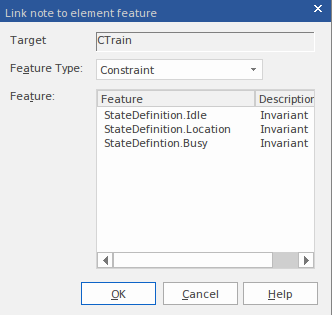
|
From the element dialog, choose 'Constraints' from the drop combo. Any defined State Definitions will be listed for you to choose from. |
|
Repeat |
Repeat the procedure for any other State Definitions on the class. |