| Prev | Next |
Introducing the Sequence Diagram
The Sequence diagram has its origins in the Unified Modeling Language, and in that language has primarily been used to represent interactions between components in software centric systems. Its usage has been broadened in the context of Systems Engineering, where it is used in a more generic way to represent the time-sequenced exchange of messages and signals between structural units of a system or part of a system.
The Sequence diagram has two axes; by convention the horizontal (x) axis represents the Block (Instances) that participate in the interaction and the vertical (y) axis represents time. The Blocks do not have to be ordered in any prescribed way, but a modeler will typically place them in the order that is most illustrative and that order is often based on when they are used in the interaction. Time does not run on a linear scale and the time scale between any two diagrams could be quite different. For example, the time scale on Sequence diagram representing a high speed photographic system would be very different to the scale on a diagram representing a grocery checkout machine. This diagram shows the location of two Sequence diagrams ('Start Vehicle Black Box' and 'Start Vehicle White Box') that are child nodes of a Use Case named 'Start the Vehicle'.
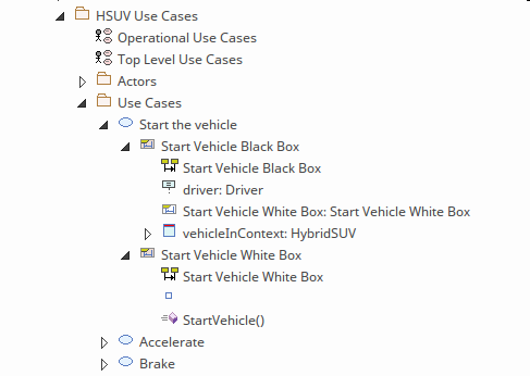
The tree structure acts as a navigation aid, and by double-clicking the item in the Browser window you would open the diagram from this view.
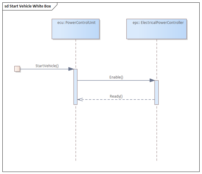
In the second diagram we see a simple Sequence diagram that represents the sequence of messages involved in starting a vehicle. It can be seen from the diagram that there are two Blocks (Instances) that form part of the interaction, and messages are exchanged between the two Blocks and the initiator of the interaction, and ultimately the Use Case.
Creating Sequence Diagrams
A Sequence diagram can be created from a number of places in the User Interface by using:
- Design ribbon - Add Diagram Icon on the Diagram Panel
- Browser window Toolbar - New Diagram Icon
- Browser window Context Menu - Add Diagram
We will use the Design ribbon to create a Sequence diagram. Firstly you will need to select the location in the Browser window where you want the Sequence diagram to be created. As with all diagrams, this can be either a Package or an element, but it is common to add Sequence diagrams to a Package as it typically involves a number of objects in the Package. Once the Package location has been selected in the Browser window, select:
Ribbon: Design > Diagram > Add

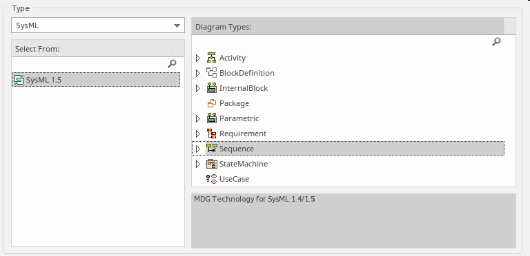
Selecting this option will open the 'New Diagram' dialog allowing you to name the diagram; initially the name will default to the name of the Package or element that contains the diagram. With the SysML perspective chosen and the version of SysML selected a list of diagrams will be displayed, allowing the selection of the Sequence diagram. Once the is selected a new Sequence diagram will be created in the location selected in the Browser window. The diagram canvas will be opened allowing you to start adding elements and connectors that describe the important interactions between objects. Enterprise Architect will also display the Sequence diagram Toolbox pages that contain the elements and relationships defined by the SysML specification as applicable for constructing Sequence diagrams. Any number of other Toolbox pages can be opened if required, in addition to the Common Elements and Common Relationships pages that will always be available.
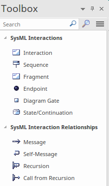
The most import elements and connectors used with the Sequence diagram are:
Elements
- Interaction
- Sequence
- Fragment
- Endpoint
- Diagram Gate
- State/Continuation
Connectors
- Message
- Self Message
- Recursion
- Call from Recursion
Elements can be added to the diagram by dragging-and-dropping them from the Browser or from the Toolbox onto the diagram canvas. The typical process is to reuse existing elements such as Blocks, which have behaviors in the form of operations that can be selected as the basis for the messages that are exchanged between lifelines. The elements can be added to the diagram as a link but more typically they are added as a lifeline.
Once a basic diagram has been created, and as knowledge of the domain and the system's interactions are further revealed, it is possible to add Fragments, Endpoints, Diagram Gates and State/Continuation elements.