| Prev | Next |
Modeling Structural Features
Blocks typically are defined using a series of structural features. These are the properties of the Block and define the nature of the Block. For example, a train engine (Rolling Stock) will have properties such as Engine Class, Identity Number, Number of Wheel Assemblies, Motive Force, Motors and a range of other properties. An important point to remember is that the Block is a classifier that describes a set of Engines. The engine at the front of the train set that you board for your summer holiday is an instance of an engine and it will have a particular Class, for example OSE class 660, and an identifier of SM-09873, and 8 wheel assemblies.
Enterprise Architect supports three basic kinds of structural feature and each is important for modeling different aspects of the structure of a Block. We will look at each of them in these sections.
- Parts - a block is composed of parts
- References - refer to features of other blocks
- Values - describe quantities
This diagram shows all three types of structural feature.
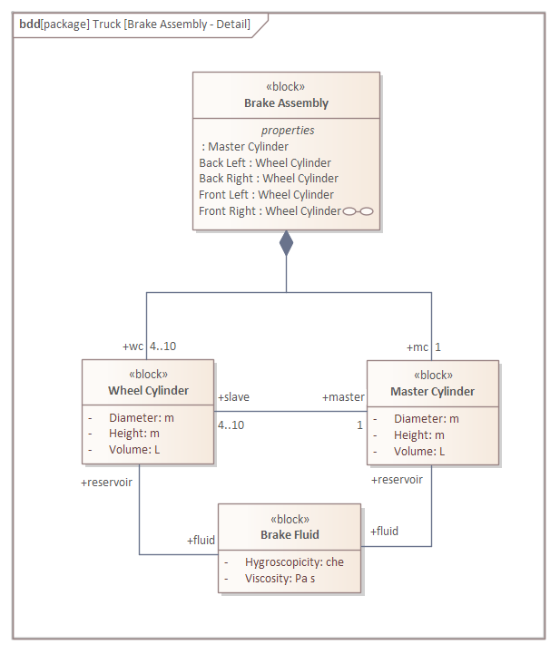
The Braking System is made up of a number of parts, two of which have been shown on this diagram. The Part Association has been used to indicate that the Master Cylinder and Wheel Cylinders are fundamental constituents of the braking system. A Reference Association has been used to show both a relationship between the two types of cylinders and also between the cylinders and the Brake Fluid. Values that have been entered as attributes are displayed with their accompanying Value Types; for example, Volume has a Value Type of L, which is the symbol for the Dimension of Volume whose SI Unit is Litre.
Blocks Composed of Parts
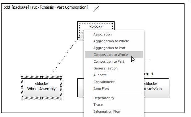
A Part is a structural Feature of a Block and forms one of the strongest relationships between a Block and its properties. It is important to understand that an Instance of a Block might have multiple instances of a Part; for example, a truck might have multiple wheel assemblies and - depending on the size and type of truck - this could be as low as 2 or as high as 10. These possible configurations can be specified in the definition of the Block and its Parts, which are formally known as multiplicities - the lower number is referred to as the lower bound and the higher number as the upper bound. A Part will typically be typed by another Block, thus in the example the type of the Part will be another Block named 'Wheel Assembly', which would typically itself comprise an axle and two wheel assemblies. Thus each Part will be defined in the Block with a name, a type and a multiplicity. The tool allows the Part Composition relationship to be created in a number of ways, but perhaps the most immediate way is to drag both the Chassis Block (the whole) and the Wheel Assembly Block (the Part) onto the diagram and then use the Quick Linker to drag from the Part (Wheel Assembly) to the whole (Chassis).
Dragging from the source object to the target will display a menu of possible connectors, and the engineer would choose the Composition to Whole connector. The result will be a relationship with the diamond marker at the Chassis end of the line, indicating it is the whole and the element at the Wheel Assembly end is the Part.
The connector properties will allow you to set the source role and multiplicities which, as discussed, specify the name and the possible number of Parts for each Instance of a Chassis.
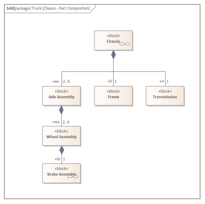
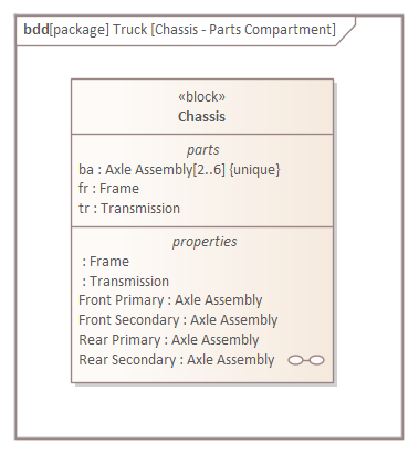
In the diagram the modeler has expressly defined the Parts by using the Part Association, available from the SysML Block Definition toolbox.
In this diagram the modeler has used the Owning Block's Part compartment to display the Parts owned by the Chassis Block.
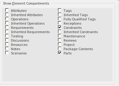
The Parts compartment will display by default, but its visibility can be controlled at a diagram level using the diagram Properties, or at an individual element level using the element's 'Compartment Visibility' option on the element's context menu. Setting the visibility at the diagram level will result in all elements in the diagram complying with the specified visibility - displayed or not displayed as specified - whereas setting it at the element level will only affect the selected element.
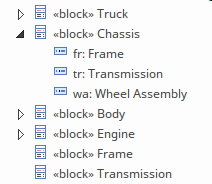
The repository elements will be updated regardless of whether they are edited in the diagram or the Browser or any other window. In the example, the engineer created the Parts in the diagram by dragging a Part Association from the Toolbox; in response to this Enterprise Architect creates three new Parts, which are placed under the Chassis node in the Browser as indicated in this screen shot.
The Part Association is the strongest type of Association relationship - the strength continuum from weakest to strongest being:
- Reference Association
- Shared Association
- Part Association
We will explore the other relationships in later sections of this guide.
References to Other Blocks
As stated earlier the Part Association is the strongest type of relationship in the SysML and implies a sense of responsibility on the part of the whole:
- It is responsible for the lifetime of its parts from which it is comprised
- A part can only participate in a part composition with a single block
The second condition means that the multiplicity at the whole end of a Part composition is always 1..1 which can be abbreviated as 1.
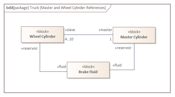
There is however another relationship, the Reference Association (or Reference for short) that can be used to specify relationships between Blocks independent of composition or the notion of one block being a part of another. This provides a very useful mechanism for creating relationships between blocks that are part of different part hierarchies or between any two blocks that are related to each other. For example the Master Cylinder and Wheel Cylinders both have a relationship to Brake Fluid which is used to fill their reservoirs. The Wheel Cylinder could in turn have a relationship to a mechanic that periodically checks the cylinder for leaks that would compromise the efficacy of the braking system. `
Values used to Describe Quantities
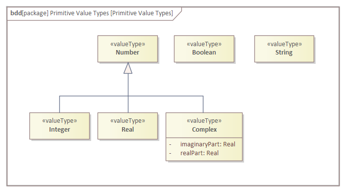
Blocks can have properties with some type of quantifiable value; for example, an Engine has a Power Output, a Reservoir has a Volume, an Automobile has a Color, a Railway carriage has a number of Bogies. The types can be a primitive type defined as Number, Integer, Real, Complex, Boolean or String, as illustrated in this diagram.
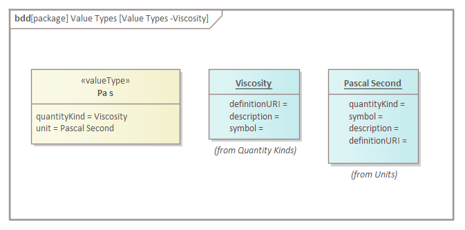
An engineer, team or community of practice can also define any number of Value Types that can be simple or structured. These can be based on any number of Systems of Units, such as the International System of Units (SI). An automotive engineer designing a braking system might find themselves using a number of Standard SI Value Types and a number of Derived Types, as well as other Values not defined as part of that standard. This diagram illustrates how these Values can be defined, using the Value Type element available in the SysML Block Definition Toolbox.
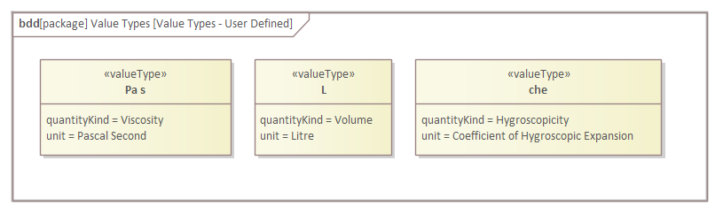
The Value Type has two defined properties - the quantityKind and the Unit. These can also be modeled in Enterprise Architect and give rigor to the application of the Value Type. An engineer will know that the type is based on a quantity (dimension) and a defined Unit. This diagram shows these elements for the (Viscosity) Value Type.