| Prev | Next |
SysML Sequence Diagram
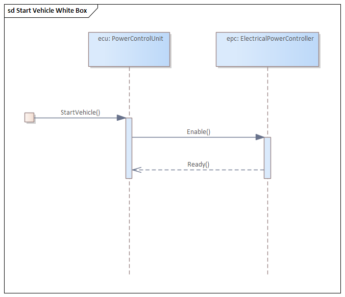
A SysML Sequence diagram, as for a UML Sequence diagram, is used to display the interaction between users, screens, objects and entities within the system. It provides a sequential map of messages passing between objects over time. Frequently, these diagrams are placed under Use Cases in the model to illustrate the Use Case scenario - how a user will interact with the system and what happens internally to get the work done.
A Sequence diagram is a form of Interaction diagram, which shows objects as Lifelines running down the page, with their interactions over time represented as Messages drawn as arrows from the source Lifeline to the target Lifeline. Sequence diagrams are good at showing which objects communicate with which other objects, and what messages trigger those communications.
Elements
The main elements that can appear in Sequence diagrams are:
- Sequence
- Fragment
- Endpoint
- Interaction
- Diagram Gate
- State/Continuation
Connectors
The main connectors that can appear in Sequence diagrams are:
- Message
- Self Message
- Recursion
- Call From Recursion
Notes
The Lifelines on a Sequence diagram must be Objects (even though you can drop elements themselves as Lifelines onto a Sequence diagram, using Objects is more compliant as a UML construct), so when you drop a Block onto the Sequence diagram, in the 'Paste Element' dialog select the 'as Instance of Element (Object)' option. This creates a new object in the diagram's parent Package, based on the selected Block element. You then create the Messages between the Objects.