| Prev | Next |
Tracing Requirements
Most Requirement processes mandate that Requirements are traced from high level concepts such as Business Drivers, Visions and Goals down to the parts of Components that implement them. For many projects this is an intractable problem because much of the information lives in a set of heterogeneous tools such as word processor documents, spreadsheets, diagram tools, corporate presentation tools and more. Some Project Managers attempt to solve the problem by creating a spreadsheet that acts as a register of all the disparate information but the management of this file takes up considerable project resources and the file is almost impossible to keep up to date. With Enterprise Architect there is the ability to model all of this project information in the one tool and to create easy-to-maintain and analyzable traces between all the elements, from the organization's mission statement right down to the level of programming code, if required.
Visualizing Traces in diagrams
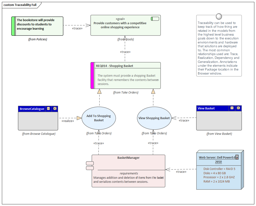
Regardless of whether you have entered the project’s Requirements using a diagram, using a text-based tool such as the Specification Manager, or by importing them from another tool, viewing the requirement traces in a diagram gives an easily understood view of their relationships. The diagrams can be created easily by dragging and dropping elements from the Browser window, or automatically by using the 'Insert Related Elements' option. This function can be configured and used to draw a graph of elements to any depth, and can be restricted to selected types of element and connector. It is a handy productivity tool in a team environment, and even modelers with deep knowledge of the domain and the repository are surprised at the connections that are displayed in the diagrams.
Visualizing Traces using the Relationship Matrix
The Relationship Matrix provides an alternative way of visualizing the relationships between Requirements and other elements, or even between different levels or types of Requirement. It is quite common for some stakeholders to prefer a spreadsheet-like view of the Requirements and their relationships, and the Relationship Matrix provides an excellent way of presenting the relationships without resorting to a diagram. In Use Case driven requirements methods, Use Cases are said to realize one or more Requirements, and these relationships can be displayed visually in the Relationship Matrix. The list of Use Cases would appear on one axis of the matrix and the Requirements would be listed on the other axis. A marker in the intersection of a row and column would display if a relationship exists, indicating that a particular Use Case realizes a Requirement. Relationships between elements can be created or deleted using the Relationship Matrix, and the Matrix can be saved and reopened at any time or saved to a CSV file so it could be opened in a spreadsheet. Documentation can also be created that includes the Relationship Matrix, providing a useful communication tool for people who do not have access to the model.

Visualizing Traces using the Traceability Window
While diagrams and the Relationship Matrix allow modelers to view traces between requirement elements it is possible that the creators of these views of the repository have deliberately omitted elements from the view. For example a diagram does not need to show all the requirements owned by a particular stakeholder. The Traceability window will, however, present a complete and unabridged view of the relationships between elements. The element relationships will be displayed regardless of the location of the elements in the Browser window.

Visualizing Traces using the Relationships Window
Modelers often choose to hide one or more relationships on a diagram for the purpose of making the diagram simpler to understand or to hide detail. The Relationships window is a useful window to have open as it will display all the relationships that exist between the elements in the diagram indicating whether they are visible or hidden in the diagram.

If relationships have been hidden in a diagram they can be made visible by selecting the 'Show Relationships' option on the 'Connectors' page of the 'Properties' dialog for the diagram.