| Prev | Next |
SysML StateMachine Diagram
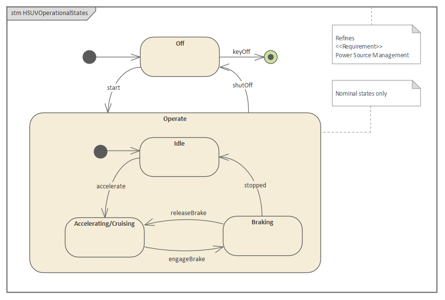
A StateMachine diagram is an ideal vehicle for presenting information about the lifetime of a system element such as a Block, which might have complex behavior and might have life cycles that are difficult to understand. The diagram can be used to describe the important conditions (States) that an entity might pass through during its lifetime or life cycles. Typically, only entities that have important stages in their lifetime are modeled with StateMachine diagrams. The entity is said to transition from one State to another as defined by the StateMachine. Triggers and Events can be described that allow the State transition to occur, and Guards can be defined that restrict the change of State. Each State can define the behaviors that occur on entry to the State, while existing in the State, and on exit from the State.
Elements
The main element types that can appear in StateMachine diagrams are:
- State
- StateMachine
- Initial
- Final
- Choice
- Junction
- Entry
- Exit
- Terminate
- History
- Fork and Join
The main connector types that can appear in StateMachine diagrams are:
- Transition
- Dependency
Tools
A wide variety of tools are available for working with StateMachine diagrams, in addition to the StateMachine diagram itself. These include:
- State Table Editor - which allows the StateMachine diagram to be visualized in a table that - for some analysts - is easier to understand than a diagram; it contains the same information as the diagram and can be viewed in a number of different ways
- Dynamic Simulation - which allows processing through StateMachines to be visualized, showing how an entity transitions from one State to another
- Executable StateMachines - which, as well as utilizing the simulation engine and allowing StateMachines to be visualized, provide a complete language-specific implementation that can form the behavioral 'engine' for multiple software products on multiple platforms