| Prev | Next |
The Construction Diagram
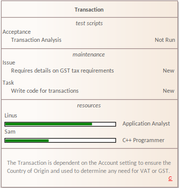
A Construction diagram is a graphical version of the 'Details' tab of the Inspector window. It shows the assigned characteristics and features of the selected element, where these features have been created. Each type of feature is shown in a separate element compartment.
To access a Construction diagram for an element, either:
- In a diagram, right-click on the element | New Child Diagram | Construction Diagram, or
- In the 'Project' or 'Context' tab of the Browser window, right-click on the element | Add | Construction Diagram
To create a new Construction diagram for multiple elements:
- Select a Package in the Browser
- Select 'Add Diagram' from the Browser context menu
- Set the Perspective to 'ALL Perspectives'
- Select 'Extended' in the 'Select From' pane
- Select 'Construction' in the 'Diagram Types' pane.
The Construction diagram for the element displays a 'C' in the bottom right corner of the element, indicating that it is the Construction rendition of the element. The list of potential properties displayed in compartments on an element include:
- Tags
- Requirements
- Constraints
- Testing
- Maintenance
- Discussions
- Reviews
- Resources
- Projects for Decisions, Events, Issues and Tasks
- Notes
- Package Contents
The visibility of compartments is dependent on there being detail in the specific features.
The possible compartments shown on the element are user-selectable from a range of element compartments. To alter this;
- Click on the diagram (or press )
- In the Properties window, select 'Elements'
- Tick the options in the 'Show Compartments' group.
An example of a Construction diagram with multiple elements.

Note that an Actor element defaults to the Rectangular Notation on a Construction diagram.