Author Topic: Multiple state machines for semi-independet objects in one diagram  (Read 537 times)

Martin Merkel

  • EA User
  • **
  • Posts: 23
  • Karma: +0/-0
    • View Profile
Hi,
I am currently trying to find a solution for the following problem: Essentially I have two (or more) independent classes, respectively objects. In my case that would be a boot loader (BL), whose lifecycle is described by one state machine, and one (or more) application(s) (APP) which are again described by their own state machine(s). They all execute on the same controller, but never at the same time. So either the boot loader executes or one of the applications. I tried to model that with entry and exit points for each of the state machines but are not able to get all this onto one diagram.
I tried to create invocations as states of the two state machines to show that if I exit the BL I enter the APP, and vice versa. I can model the transitions from an exit point on one STM to an entry point on the other STM, but in this way I 'loose' the states of the STMs in the diagram. Only entry and exit point are taken over as structural elements.
Any hints to solve this are welcome.
Martin
« Last Edit: June 26, 2025, 11:10:19 pm by Martin Merkel »

PeterHeintz

  • EA User
  • **
  • Posts: 976
  • Karma: +58/-18
    • View Profile
Re: Multiple state machines for semi-independet object in one diagram
« Reply #1 on: June 25, 2025, 03:33:42 pm »
Hi,
I do not know what you mean by this.
"but in this way I 'loose' the states of the STMs in the diagram."
and why you need the "entry" and "exit" at all.
I assume your boot loader is starting when you controller is released from reset. This could be a state machine on top of your stuff which is represented there as an invocation state, calling your state machine having again the invocation states for your state machines representing the boot loaded and the aplication.
Best regards,

Peter Heintz

Martin Merkel

  • EA User
  • **
  • Posts: 23
  • Karma: +0/-0
    • View Profile
Re: Multiple state machines for semi-independet object in one diagram
« Reply #2 on: June 25, 2025, 04:17:15 pm »
Yes, it is correct that starting the boot loader is when I release the controller from the reset. The boot loader is however a bit more than an initial state. For once, it checks if there is a valid application available in another sector of the non volatile memory. It may also check if there multiple applications and which one to start. I may also verify, if an application is signed. Further, it may check if there is an attempt to download firmware update, an perform authentication of any entity that attempt a application firmware update. A boot loader can be considered as a separate object that is build independent of the applications. So logically we thought once I've done my boot loading tasks, I set the reset vector to any of the applications and then perform the reset, thus the exit point in the STM.
This would look sort of like this (using invocations of the STMs):
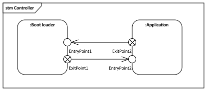


What I meant with 'loose' is that with an invocation I create instances of the STMs an entry/exit point are retained but the states of the individual STMs are not instantiated.

What I am aiming for that in a diagram similar to above, I see the individual STMs with their sub-states (as in particular application STMs can get quite complex (for example for medical devices) and no outer STM frame. Those STMs below are extremely oversimplified.
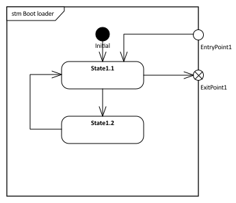
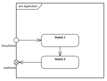
 

Below the simple EA project
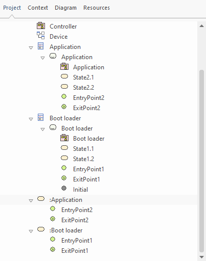


Ps: What I'm looking for goes a bit into this direction:
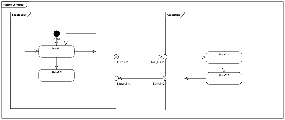


I used a custom diagram and created links of the STMs on that. Changed then to 'New Child Diagram -> Show Composite Diagram in Frame' and disabled 'Filter to Toolbox'. Definitely cheating, however the transitions from and to the states do not end at the entry and exit points but in nowhere...
« Last Edit: June 25, 2025, 05:23:40 pm by Martin Merkel »

PeterHeintz

  • EA User
  • **
  • Posts: 976
  • Karma: +58/-18
    • View Profile
Re: Multiple state machines for semi-independet object in one diagram
« Reply #3 on: June 26, 2025, 05:15:05 pm »
Well, I think you could achieve that be composite states.
I have already modeled several controllers, processors and FPGA’s but following this approach would lead for me to composite states in composite states in composite states,….
Therefore, I build a state machine tree based on invocation states, and so I do not have the goal to show all on one diagram. Instead, I add a “Composite Diagram Link” to each called state machine. The bad thing in EA is, that it allows for whatever reason only setting the diagram link before the invocation is defined.
By the way, for all that stuff I never had the need to use “Entry” and “Exit”. Those elements I only need in very very exceptional cases.
Best regards,

Peter Heintz

Martin Merkel

  • EA User
  • **
  • Posts: 23
  • Karma: +0/-0
    • View Profile
Re: Multiple state machines for semi-independet object in one diagram
« Reply #4 on: June 26, 2025, 07:31:18 pm »
Hi,
thanks for the feedback. The reason why I'm trying to use entry and exit points was basically that in this specification working group one of the colleagues (who at the end also provided the diagrams in the specification) present a diagrams with two STMs and direct transitions between those STMs from an internal state in one STM to an internal state in the second STM. This looked a bit strange to me, thus I suggested the entry and exit point to at least indicate that the lifecycle of for example the boot loader has ended, and the application is invoked, or vice versa. He uses StarUML that obviously permits such things, even without the entry and exit points.
Composite states may be an approach, however if I add to states to a diagram and add the two STMs created earlier as child diagrams, I just get the indication the those states are composite and do not see the sub states. I can switch to Show Composite Diagram in Frame/Compartment, but then I end up again with the transitions out of and into the STMs are hanging around in nowhere. This will not allow me to create distinct transitions from one STM to the other, in particular when I would have multiple entry points into an STM.
I haven't quite understood why EA obviously permits to define entry and exit point for state machines, but offers not much that one could do with them.
What is definitely required that I see all the possible state machines and their (sub)states in one diagram as those diagrams need to be presented to certification bodies (I cannot send them a EA model) to formally assess safety or security fitness, at least for some applications (I mentioned medical earlier).
Thanks, Martin

Martin Merkel

  • EA User
  • **
  • Posts: 23
  • Karma: +0/-0
    • View Profile
Multiple state machines for semi-independet objects (Solved, sort of)
« Reply #5 on: June 28, 2025, 12:22:52 am »
I think I have found a solution, although I do not fully understand it.
In my earlier trials, I started to work from a class, added the STM and populate it will all my states. That ended up in the strange diagrams I posted earlier. Now I use an empty STM diagram and drop the two STMs from the toolbox onto it. I can add my states, entry and exit points and the transitions I need. As long as I only work in this diagram things are fine. When I started to work in the two individual composite STM diagrams, things get messy. But as long as I stay in the main diagram, I think I can get what I want.


PeterHeintz

  • EA User
  • **
  • Posts: 976
  • Karma: +58/-18
    • View Profile
Re: Multiple state machines for semi-independet objects in one diagram
« Reply #6 on: June 28, 2025, 12:58:36 am »
Might look graphically nice, but it is from my perspective neither an ULM nor a SysML state machine!
Best regards,

Peter Heintz

Martin Merkel

  • EA User
  • **
  • Posts: 23
  • Karma: +0/-0
    • View Profile
Re: Multiple state machines for semi-independet objects in one diagram
« Reply #7 on: June 28, 2025, 03:27:59 am »
As said, I'm not at all convinced that it is correct. If I deselect the Show Composite Diagram in Frame I get the normal notation with the composite indication in the bottom right corner. But at least it may help to indicate that only one of the objects it existing at any point in time. You exit one STM and with that the other object enters its lifecycle.