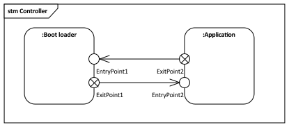
Yes, it is correct that starting the boot loader is when I release the controller from the reset. The boot loader is however a bit more than an initial state. For once, it checks if there is a valid application available in another sector of the non volatile memory. It may also check if there multiple applications and which one to start. I may also verify, if an application is signed. Further, it may check if there is an attempt to download firmware update, an perform authentication of any entity that attempt a application firmware update. A boot loader can be considered as a separate object that is build independent of the applications. So logically we thought once I've done my boot loading tasks, I set the reset vector to any of the applications and then perform the reset, thus the exit point in the STM.
This would look sort of like this (using invocations of the STMs):
What I meant with 'loose' is that with an invocation I create instances of the STMs an entry/exit point are retained but the states of the individual STMs are not instantiated.
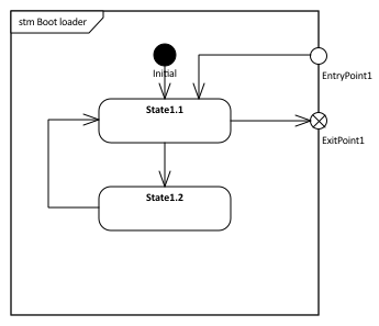
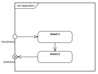
What I am aiming for that in a diagram similar to above, I see the individual STMs with their sub-states (as in particular application STMs can get quite complex (for example for medical devices) and no outer STM frame. Those STMs below are extremely oversimplified.
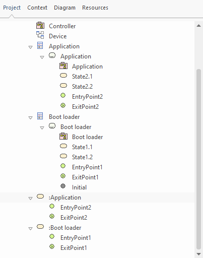
Below the simple EA project
Ps: What I'm looking for goes a bit into this direction:
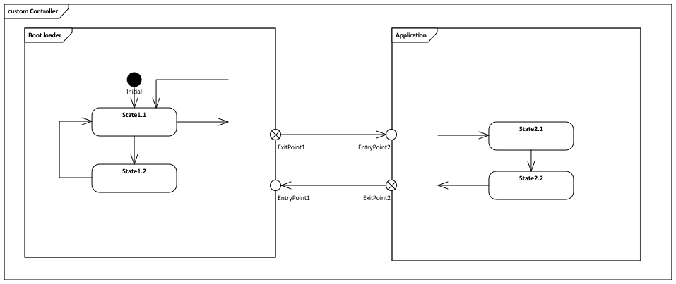
I used a custom diagram and created links of the STMs on that. Changed then to 'New Child Diagram -> Show Composite Diagram in Frame' and disabled 'Filter to Toolbox'. Definitely cheating, however the transitions from and to the states do not end at the entry and exit points but in nowhere...
 Enterprise ArchitectPro Cloud ServerProlaborate

