Introduction to ArchiMate® in Enterprise Architect
ArchiMate® is a graphical language and open standard used to describe Enterprise Architectures, developed and maintained by The Open Group®. It can be used to create a wide range of viewpoints, each relevant to different project and business stakeholders. These support the activities of business architects, data architects, solution architects, infrastructure architects and enterprise architects.
What does it do?
ArchiMate is used to describe the architecture of organizations - specifically their business processes, organizational structures, information flows, IT systems and technical infrastructure.
What are its benefits?
- ArchiMate has been designed to be lean, unambiguous, and as applicable as possible.
- Helps clarify and visualize the relationships between domains - business, application and technology.
- Helps design, evaluate, and communicate the outcomes of decisions and changes within and between domains.
- Encourages consistency across architectural models and domains.
- Allows architects to determine and plan for the potential impact of change.
How does it do it?
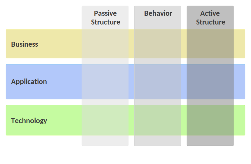
Core Framework Layers
|
|
| Business: | Business services offered to customers and business processes that support these activities, carried out by business roles within the organization structure. |
| Application: | Software applications that support business processes, the application services they offer and the interfaces between them that permit exchange of information. |
| Technology: | Communication hardware and system software needed to provide technology services to support and run the applications. |
| Active Structure: | Depicts the structural elements or "subjects of an activity" such as business actors, application components, and devices that display actual behavior. |
| Behavior: | Represents the processes, functions, events and services that are performed by structural elements. |
| Passive Structure: | Depicts objects such as information and data objects on which behavior is performed. Can also include physical objects. |
The Full ArchiMate Framework
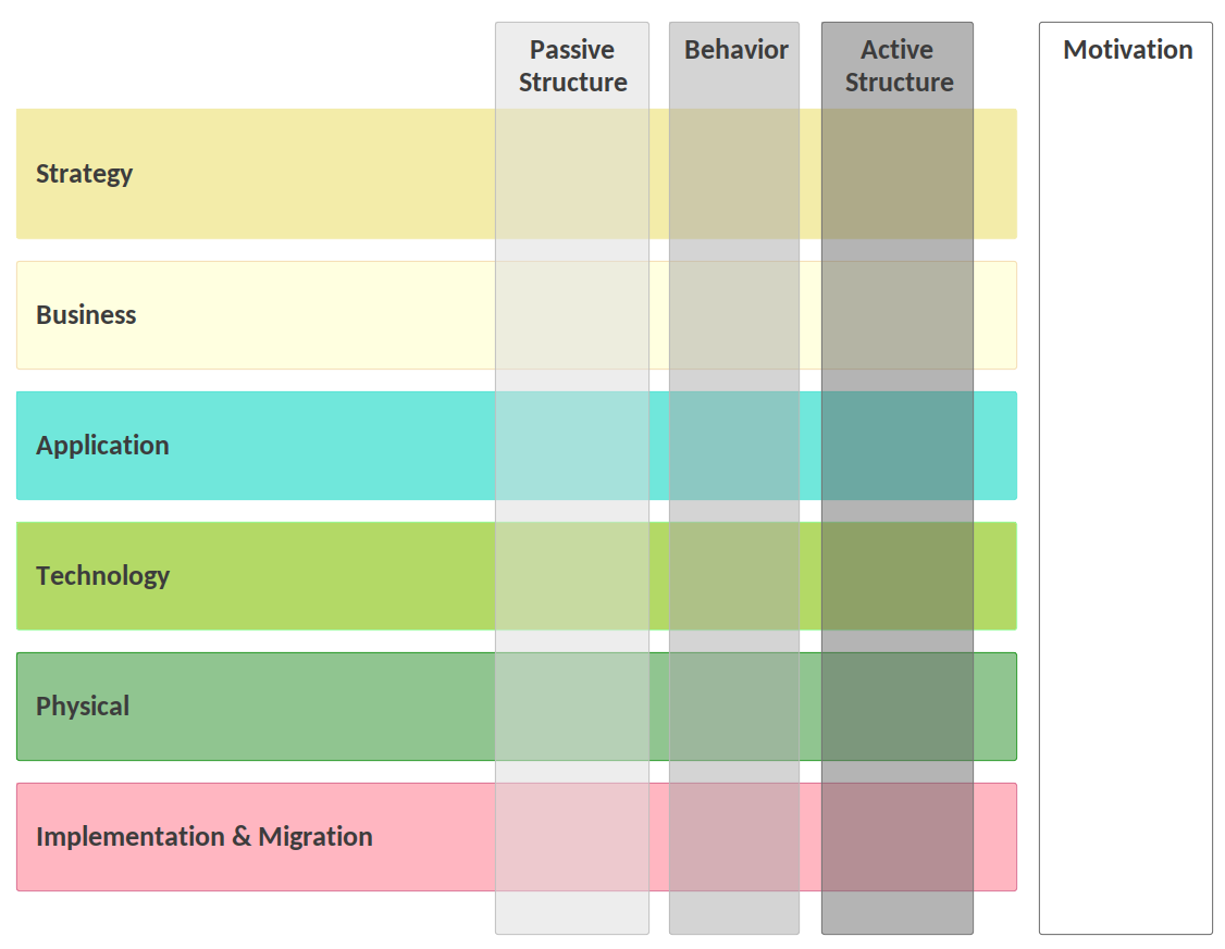
| Strategy elements are used to model an organization's capabilities, and how they need to change in order for meet desired business outcomes. |
| Physical elements have been added as an extension to the Technology Later, used for modeling physical things such as equipment, facilities, distribution networks and materials. |
| Implementation and Migration elements are used to model the implementation and migration of architectures. This includes program, portfolio, and project management, is well as a plateau element supporting migration planning. |
| Motivation elements are used to model the motivation behind business change that guides the design and evolution of architectures. |
Use of Colors
Relationships with Other Standards
TOGAF
BPMN
UML
Modeling in Enterprise Architect
Using Model Patterns
Basic Viewpoints
Organization Viewpoint
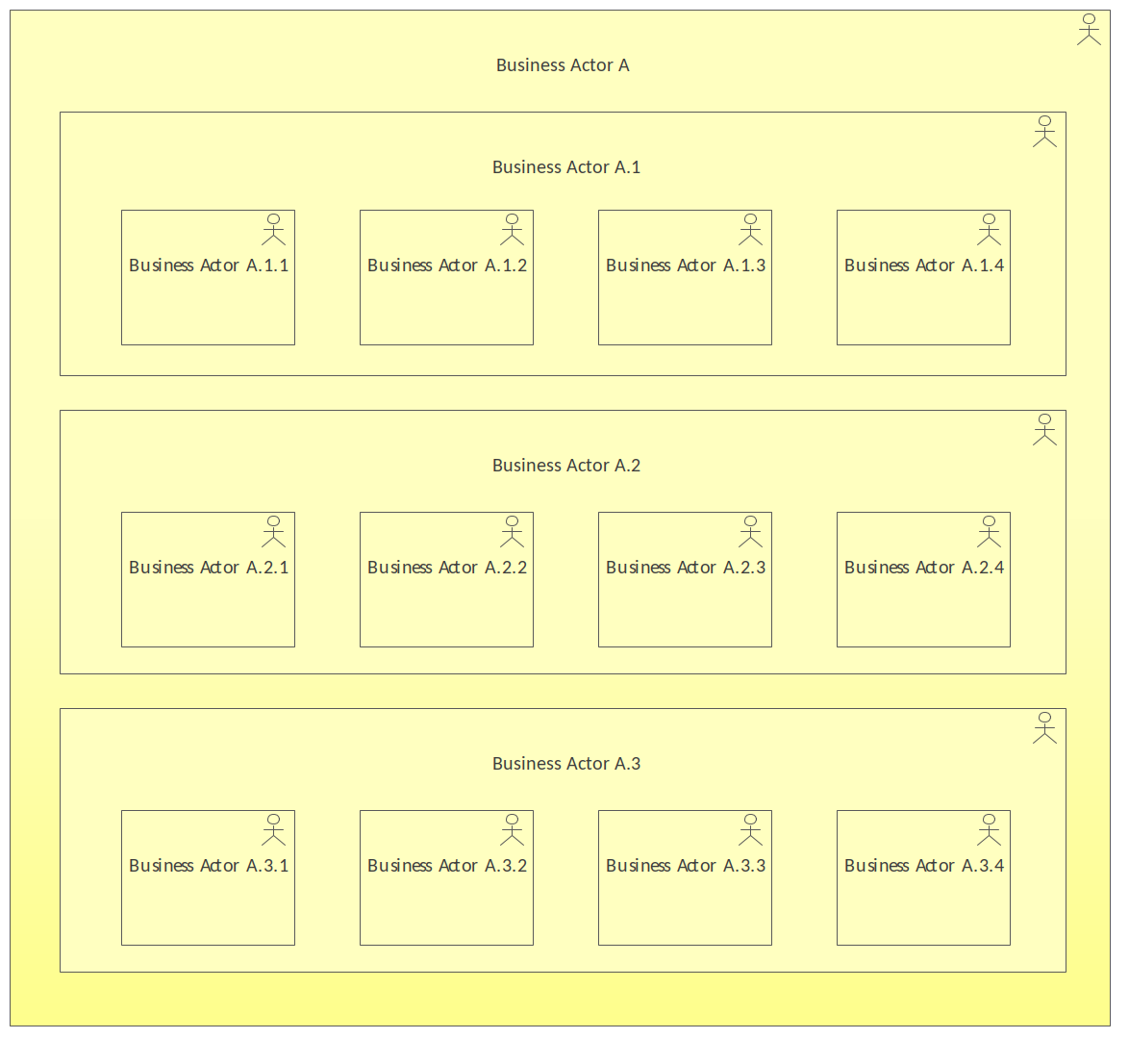
The Organization Viewpoint pattern creates elements and a diagram that describes the roles and actors of an organization or entity, or part of an organization such as a department or section. The elements are represented in a nested structure.
-
Figure 1:
Organization Viewpoint
Discussion
To provide designing, deciding and informing views for enterprise, process and domain architects, managers, employees, shareholders and others who are concerned with aspects such as identification of competencies, authority, and responsibilities
It is typically created (or imported) during the initial stages of defining an enterprise architecture and can subsequently be used by any endeavor. Many other viewpoints and models will use elements from this view.
The following is a list of some things you may want to do when working with this pattern.
- Change the name of the diagram to suit the initiative.
- Change the name of the Business Actors to suit the initiative.
- Create additional Business Actors and add other relationships as needed.
The following is a list of next steps you may want to perform after working with this pattern.
- Relate the Business Actors to other elements in the model such Capabilities or Business Processes to show responsibility, governance or other relationships.
- Use the Relationship Matrix to visualize relationships.
- Use the collaboration tools such as Discussions, Chat and Reviews to engage other modelers.
- Generate documentation of the model and diagram using the automatic document generator.
- Create Maintenance Items such as Issues, Decisions, Changes and Tasks as required.
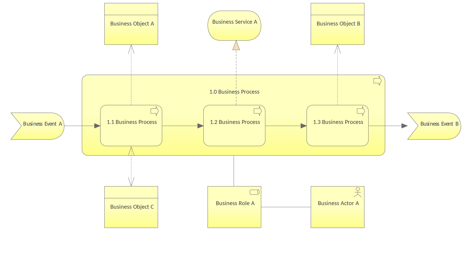
Business Process Cooperation Viewpoint
The Business Process Cooperation Viewpoint pattern creates elements and a diagram that describe the business processes showing how they relate to each other and also with their environment. This includes relationships with Business Services and Business Objects and the Roles and Actors that perform the processes or who are affected by them.
-
Figure 2:
Business Process Cooperation Viewpoint
Discussion
To provide a designing view for process and domain architects, operational managers and others who are concerned with aspects such as dependencies between business processes, consistency and completeness, responsibilities.
It can be used to visualize a high-level design of business processes within their context and to provide a view of processes dependencies and relationship with other elements that will assist stakeholders such as operation managers and process analysis teams.
The following is a list of some things you may want to do when working with this pattern.
- Change the name of the diagram to suit the initiative.
- Change the name of the Processes, Business Objects, Business Events, Business Services and other elements to suit the initiative.
- Create Additional Processes, Business Objects, Business Evens, Business Services and other elements to suit the initiative.
- Create additional relationships as needed.
The following is a list of next steps you may want to perform after working with this pattern.
- Relate the Processes to other elements in the Model including: Capabilities and Application level elements.
- Use the Relationship Matrix to visualize relationships.
- Use the collaboration tools such as Discussions, Chat and Reviews to engage other modelers.
- Generate documentation of the model and diagram using the automatic document generator.
- Create Maintenance Items such as Issues, Decisions, Changes and Tasks as required.
Product Viewpoint
The Product Viewpoint pattern creates elements and a diagram that describe the value that the products offer to external parties such as customers or other stakeholders It allows them to visualize one or more products' composition in terms of their constituent business, application, or technology services and any number of contracts or other agreements. The channels (interfaces) through which this product is offered, and the events associated with the product can also be represented in this viewpoint.
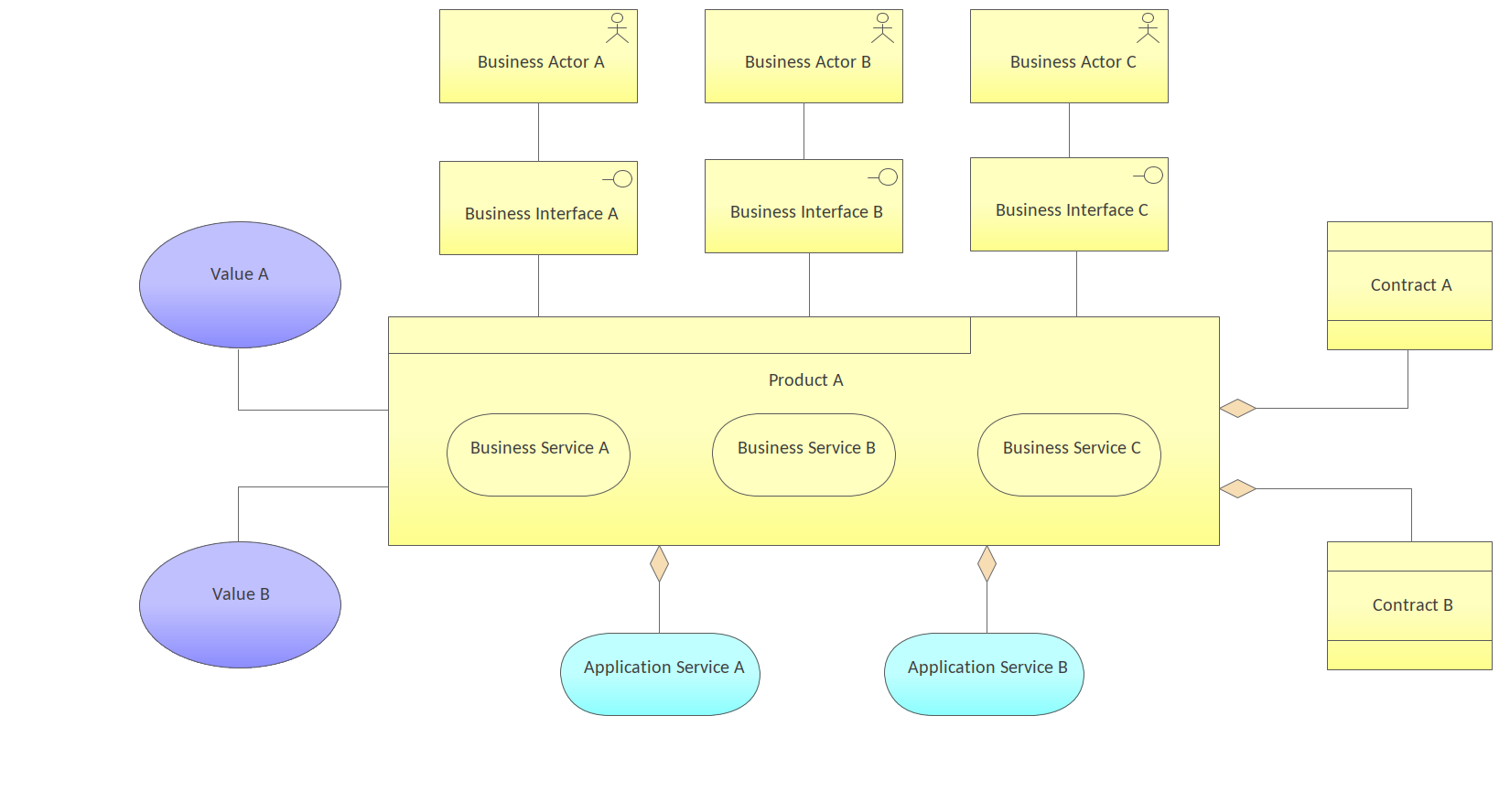
Figure 1. Shows a Business Layer Diagram with a centrally located Product related to a number of including: Values, Contracts, Business Interfaces.
Discussion
To provide a designing view for product developers, product managers, process and domain architects and others who are concerned with aspects such as product development or the value offered by the products of the enterprise.
It is typically used in product development to design and specify a product that will meet a customer's or other stakeholder's expectations. This is typically done by analysis of existing services that can be combined together or by the creation of additional services required by the product. It will form a valuable definition and specification for business process architects and others that need to design and provide the business processes and technology capability for the product to be realized.
The following is a list of some things you may want to do when working with this pattern.
- Change the name of the diagram to suit the initiative.
- Change the name of the Product and other elements to suit the initiative.
- Create additional Values, Contracts, Business Interfaces, Business Roles, and Application Services and add other relationship as needed.
- Create additional relationships as needed.
The following is a list of next steps you may want to perform after working with this pattern.
- Relate the Product element to other elements in the model including Requirements and Capabilities.
- Use the Relationship Matrix to visualize relationships.
- Use the collaboration tools such as Discussions, Chat and Reviews to engage other modelers.
- Generate documentation of the model and diagram using the automatic document generator.
- Create Maintenance Items such as Issues, Decisions, Changes and Tasks as required.
Application Cooperation Viewpoint
The Application Cooperation Viewpoint pattern creates elements a diagram that describe the relationships between applications components and their locations, the services they provide or utilize and the information that flows between them.
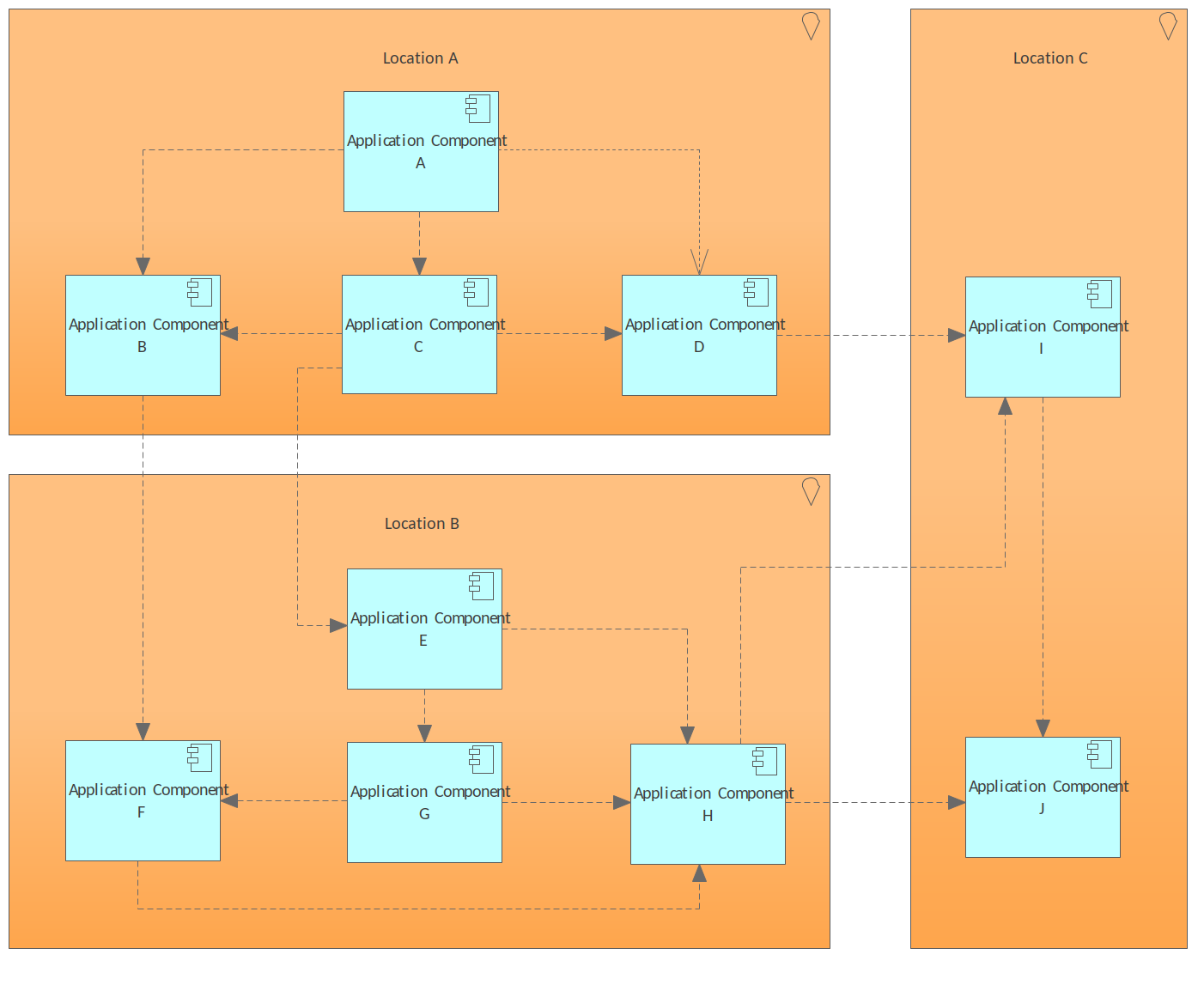
Figure 1. Shows an Application Layer Diagram that contains a number of Locations that contain Application Components that are connected by Dependency relationships.
Discussion
To provide a designing view for enterprise, process, application, and domain architects and others who are concerned with aspects such as relationships and dependencies between applications, orchestration/choreography of services, consistency and completeness, reduction of complexity.
It is typically used to create an overview of the application landscape of an organization. This viewpoint is also used to express the (internal) cooperation or orchestration of services that together support the execution of a business process.
The following is a list of some things you may want to do when working with this pattern.
- Change the name of the diagram to suit the initiative.
- Change the name of the Locations and the Application Components to suit the initiative.
- Create additional Locations and Application Components and add other relationship as needed.
The following is a list of next steps you may want to perform after working with this pattern.
- Relate the Locations and Application Components to other elements in the model.
- Use the Relationship Matrix to visualize relationships.
- Use the collaboration tools such as Discussions, Chat and Reviews to engage other modelers.
- Generate documentation of the model and diagram using the automatic document generator.
- Create Maintenance Items such as Issues, Decisions, Changes and Tasks as required.
Application Usage Viewpoint
The Application Usage Viewpoint pattern creates elements and a diagram that describes how application services and the applications that realize them are used to support any number of business processes. It can also show the relationship between that applications that implement the services.
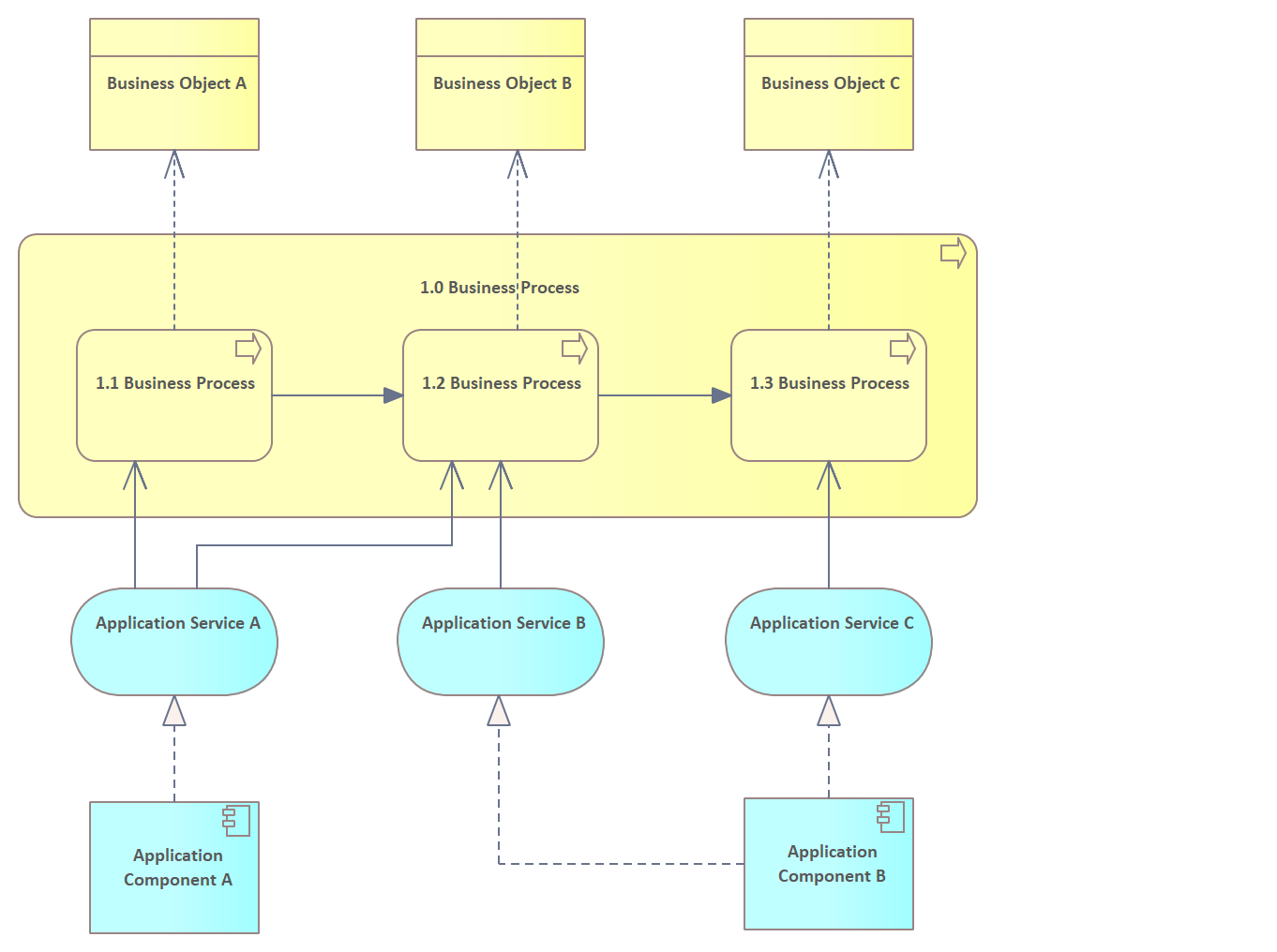
Figure 1. Shows an Application Layer Diagram with a Businesses Process containing child Processes and related Business Objects, Application Services and the Application Components that realize these Services.
Discussion
To provide a designing and deciding view for enterprise, process, and application architects, operational managers and others who are concerned with aspects such as consistency and completeness, reduction of complexity.
It is useful as in the application design discipline to identify or specify the services needed by business processes and other applications. Alternatively it can be used when designing business processes by identifying the available application services. It can also be used by operational managers who are responsible for the processes to identify and understand the application services and applications required by the process.
The following is a list of some things you may want to do when working with this pattern.
- Change the name of the diagram to suit the initiative.
- Change the name of the Business Processes, Business Objects, Application Services and Application Components to suit the initiative.
- Create additional Business Processes, Business Objects, Application Services and Application Components and add other relationship as needed.
The following is a list of next steps you may want to perform after working with this pattern.
- Relate the Processes to other elements in the Model including: Capabilities and Application level elements.
- Relate the Application Components to other Technology layer elements.
- Use the Relationship Matrix to visualize relationships.
- Use the collaboration tools such as Discussions, Chat and Reviews to engage other modelers.
- Generate documentation of the model and diagram using the automatic document generator.
- Create Maintenance Items such as Issues, Decisions, Changes and Tasks as required.
Implementation and Deployment Viewpoint
The Implementation and Deployment Viewpoint pattern creates elements and a diagram that relate programs and projects to the parts of the architecture that they implement. This view allows modeling of the scope of programs, projects, project activities in terms of the plateaus that are realized or the individual architecture elements that are affected. In addition, the way the elements are affected may be indicated by annotating the relationships.
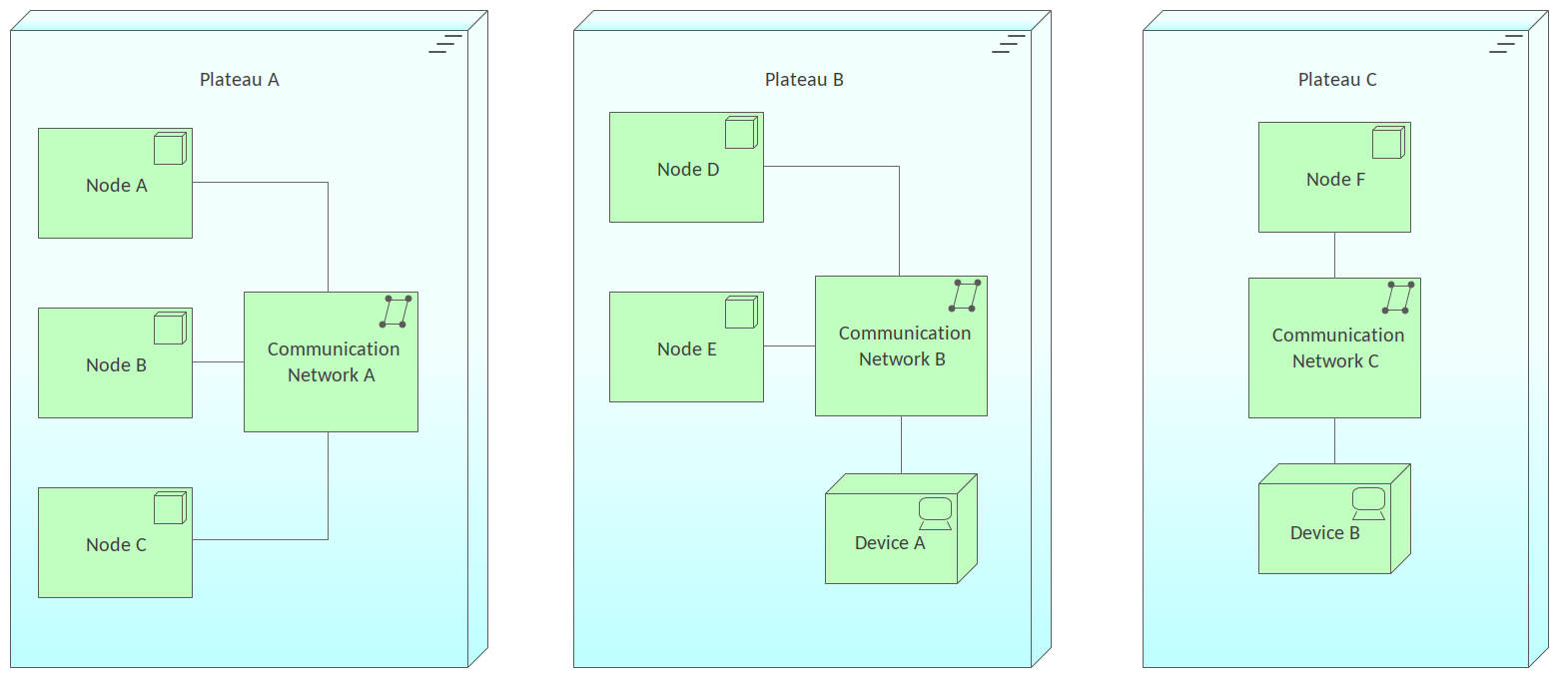
Figure 1. Shows a Deployment View where transition topologies of Nodes and Networks are described in the context of different Plateaus.
Discussion
To provide a designing view for Application Architects and Domain Architects and others who are concerned with aspects such as the structure of application platforms and how they relate to supporting technologies.
The following is a list of some things you may want to do when working with this pattern.
- Change the name of the Package and diagram to suit the initiative.
- Change the name of the Plateaus to suit the initiative.
- Change the names of the Nodes and Communication Networks.
- Create additional Plateaus and add other relationship as needed.
The following is a list of next steps you may want to perform after working with this pattern.
- Create trace relationships to up-stream model elements that the elements in this viewpoint ultimately trace back to.
- Create documentation that will help disseminate the information contained in the diagram to other team members.
Technology Viewpoint
The Technology Viewpoint pattern creates elements and a diagram that describes the software and hardware technology elements supporting the Application Layer, such as physical devices, networks, or system software such as middleware operating systems, databases and other containers.
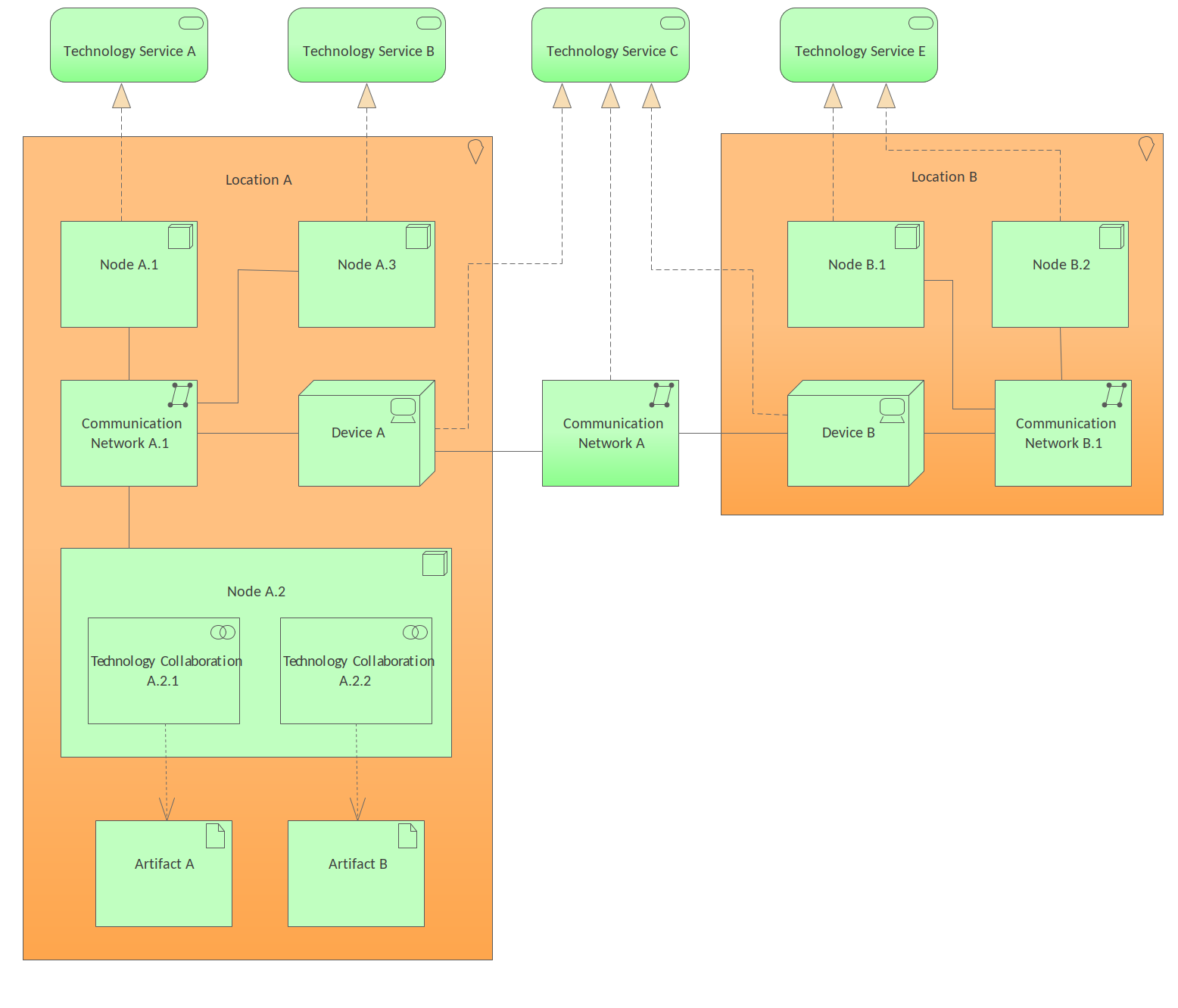
Figure 1. Shows a Technology Layer diagram that describes technology in two separate locations. The area number of Nodes and Devices connected by Communication Networks that together ultimately provide the services described by the Technology Services.
Discussion
To provide a designing view for Infrastructure architects, operational managers and others who are concerned with aspects such as stability, security, dependencies, costs of the infrastructure.
It is typically used during the design stages but could also be used at any point to describe or document the relationship between software and hardware technology elements that support the Application Layer.
The following is a list of some things you may want to do when working with this pattern.
- Change the name of the Package and diagram to suit the initiative.
- Change the name of the Locations to suit the initiative.
- Change the names of the Nodes and Communication Networks.
- Create additional Locations, Nodes, Devices, Artifacts and Communication Networks and add other relationship as needed.
The following is a list of next steps you may want to perform after working with this pattern.
- Create trace relationships to up-stream model elements that the elements in this viewpoint ultimately trace back to.
- Create documentation that will help disseminate the information contained in the diagram to other team members.
Technology Usage Viewpoint
The Technology Usage Viewpoint pattern creates elements that show how applications are supported by the software and hardware technology: the technology services are delivered by the devices; system software and networks are provided to the applications. This viewpoint plays an important role in the analysis of performance and scalability, since it relates the physical infrastructure to the logical world of applications.
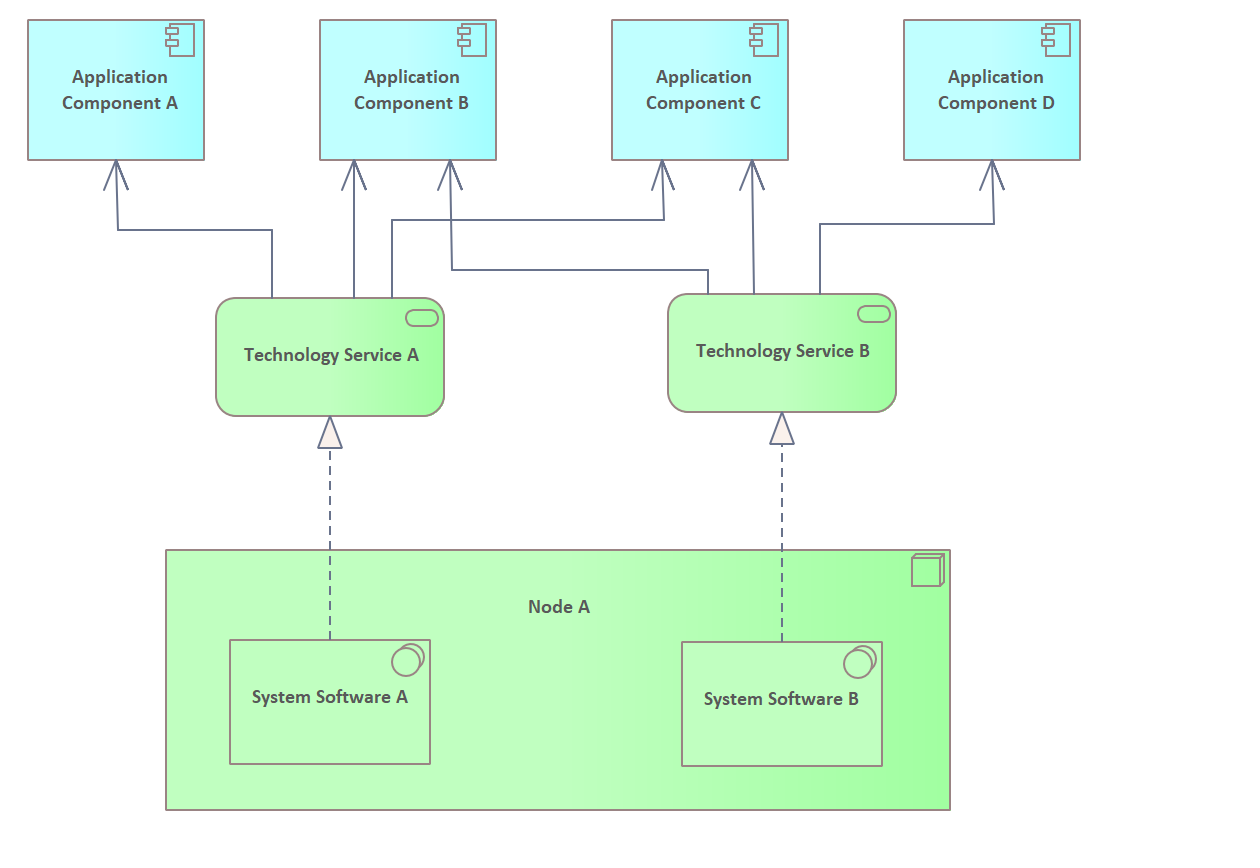 Figure 1. Shows a Technology Layer diagrams that relates Application Components to Technology Services and ultimately to the Nodes and System Software that fulfils the services.
Discussion
To provide a designing view for Application Architects, Infrastructure Architects, Operational Managers and others who are concerned with aspects such as dependencies, performance and scalability. It will assist when architects need to analyze and specify the performance and quality requirements of the infrastructure based needs of the applications that utilize it.
It is typically used during the design stages but could also be used at any point to describe or document how applications are supported by the software and hardware technology: the technology services are delivered by the devices; system software and networks are provided to the applications.
It is typically used during the design stages but could also be used at any point to describe or document the relationship between software and hardware technology elements that support the Application Layer.
The following is a list of some things you may want to do when working with this pattern.
- Change the name of the Package and diagram to suit the initiative.
- Change the names of the Nodes, System Software, Technology Service and Application Components to suit the initiative.
- Create additional Nodes, System Software, Technology Service and Application Components and add other relationship as needed.
The following is a list of next steps you may want to perform after working with this pattern.
- Create trace relationships to up-stream model elements that the elements in this viewpoint ultimately trace back to.
- Create documentation that will help disseminate the information contained in the diagram to other team members.
Information Structure Viewpoint
The Information Structure Viewpoint pattern creates elements that show the structure of the information used in the enterprise or in a specific business process or application, in terms of data types or information elements. It will assist in visualizing the information from the business level through the application level down to the infrastructure elements that implement databases and other persistent stores.
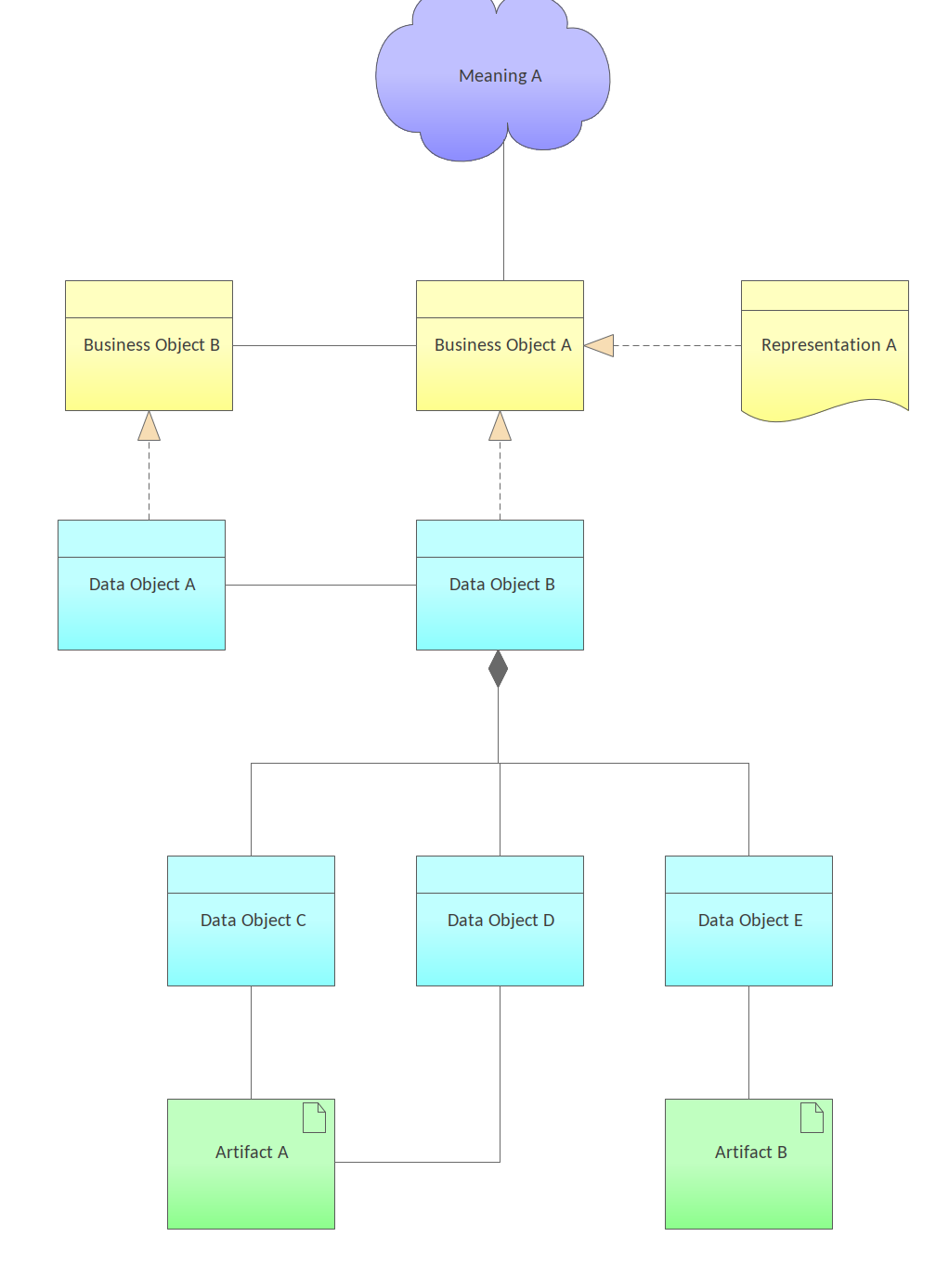
Figure 1. This Business Layer Diagram models the relationships a Meaning and the Business Objects, Data Objects and Artifacts that are used.
Discussion
To provide a designing view for Domain and information Architects and others who are concerned with aspects such as structure and dependencies of the used data and information, consistency and completeness.
It is typically used during the design stages but could also be used at any point to describe or document the relationship between information in its various forms from Business Objects, Data Objects down to Artifacts that exist at the physical schema level.
The following is a list of some things you may want to do when working with this pattern.
- Change the name of the Package and diagram to suit the initiative.
- Change the name of the Meaning and Representation elements to suit the initiative.
- Change the names of the Business Objects, Data Objects and Artifacts to suit the initiative.
- Create additional Business Objects, Data Objects and Artifacts and add other relationship as needed.
The following is a list of next steps you may want to perform after working with this pattern.
- Create trace relationships to up-stream model elements that the elements in this viewpoint ultimately trace back to.
- Create documentation that will help disseminate the information contained in the diagram to other team members.
Service Realization Viewpoint
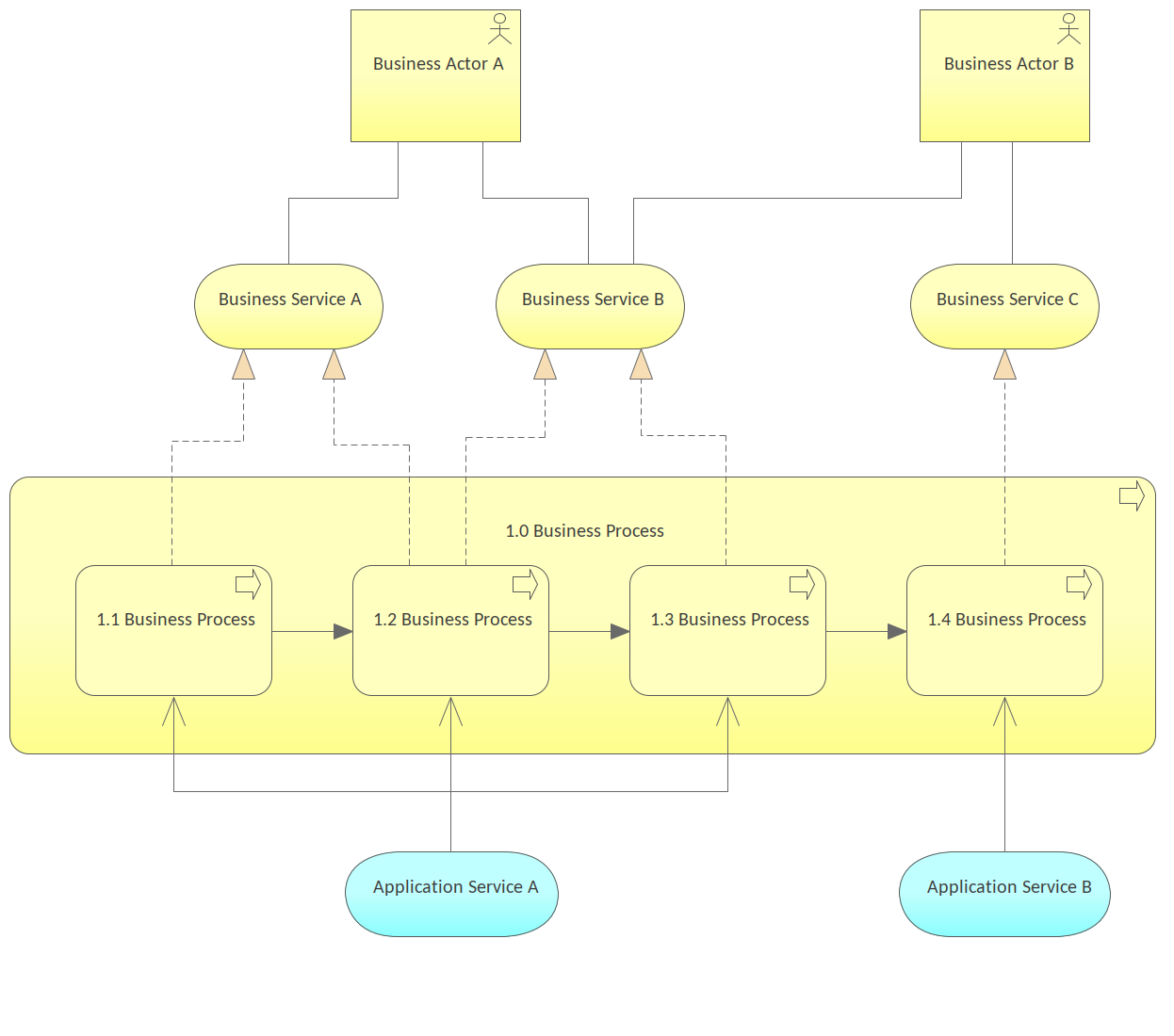
Figure 1. Shows a business Layer diagram that describes the relationship between Business Services and the Business Processes that realize them including the Application Services that ultimately realize the processes.
Discussion
To provide a designing view for Process and Domain Architects, Product and Operational Managers and others who are concerned with aspects such as added-value of business processes, consistency and completeness, responsibilities.
It is typically used during the design stages to show a view of the context of the business processes but could also be used at any point to describe or document the relationship between the Business Processes and the Application Services that implement them.
The following is a list of some things you may want to do when working with this pattern.
- Change the name of the Package and diagram to suit the initiative.
- Change the name of the Roles and Business Service elements to suit the initiative.
- Change the names of the Business Processes and the Application Services to suit the initiative.
The following is a list of next steps you may want to perform after working with this pattern.
- Create trace relationships to up-stream model elements that the elements in this viewpoint ultimately trace back to.
- Create documentation that will help disseminate the information contained in the diagram to other team members.
Physical Viewpoint
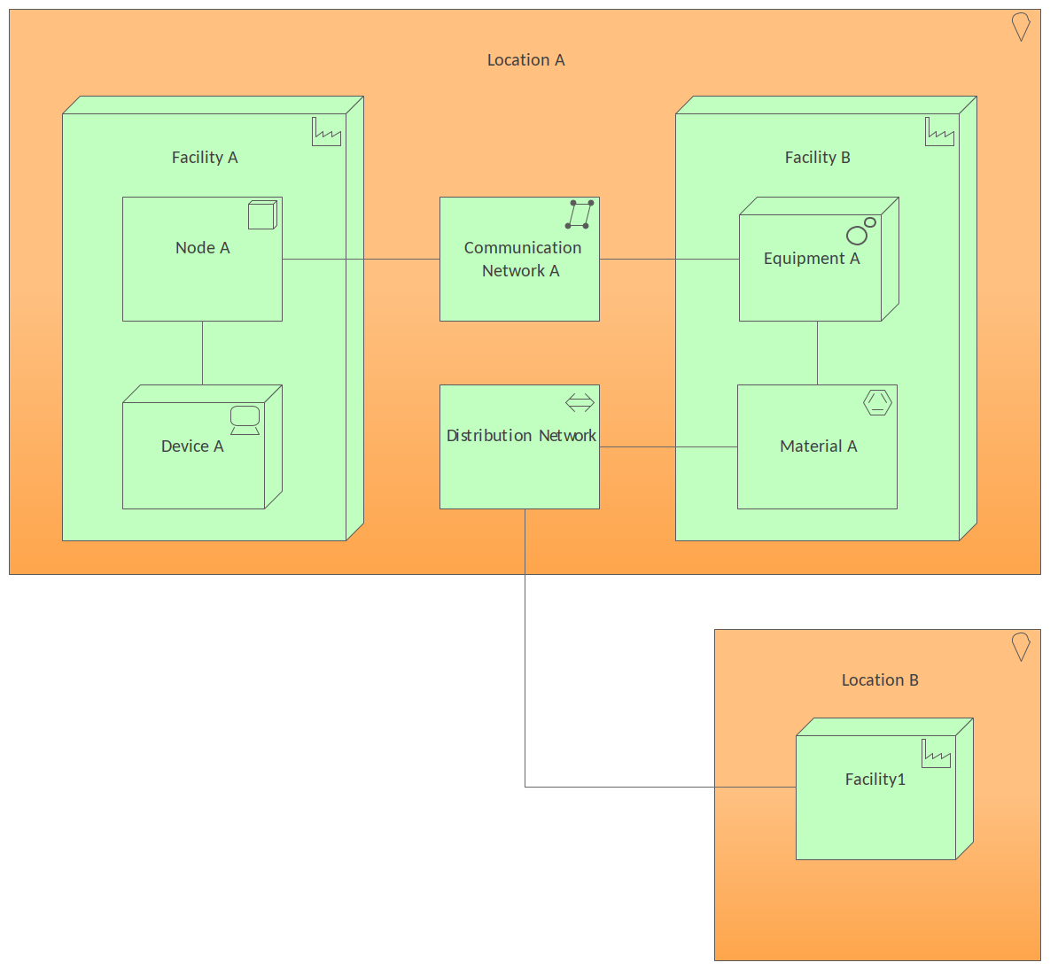
Figure 1. Shows a Technology Layer diagram that shows Location that has two facilities with a Node and an Equipment connected by a Communication Network.
Discussion
The purpose of the pattern is to allow Infrastructure Architects, Operational Managers or other Stakeholder to create or view a model that contains equipment (one or more physical machines, tools, or instruments) that can create, utilize, store, relocate, or transform materials. It also describes how the equipment is connected via the distribution network, and what other active elements are assigned to the equipment.
It is commonly constructed at the time the enterprise architecture is being articulated and can help with planning a number of aspects of the business architecture and implementation including being used as a heat map to identify areas of investment.
The following is a list of some things you may want to do when working with this pattern.
- Change the name of the Package and diagram to suit the initiative.
- Change the name of the Location and Facilities to suit the initiative.
- Change the name of the Node, Device Equipment and Material to suit the initiative.
- Change the name of the Communication Network and Distribution Network to suit the initiative.
The following is a list of next steps you may want to perform after working with this pattern.
- Create trace relationships to up-stream model elements that the elements in this viewpoint ultimately trace back to.
- Create documentation that will help disseminate the information contained in the diagram to other team members.
Layered Viewpoint
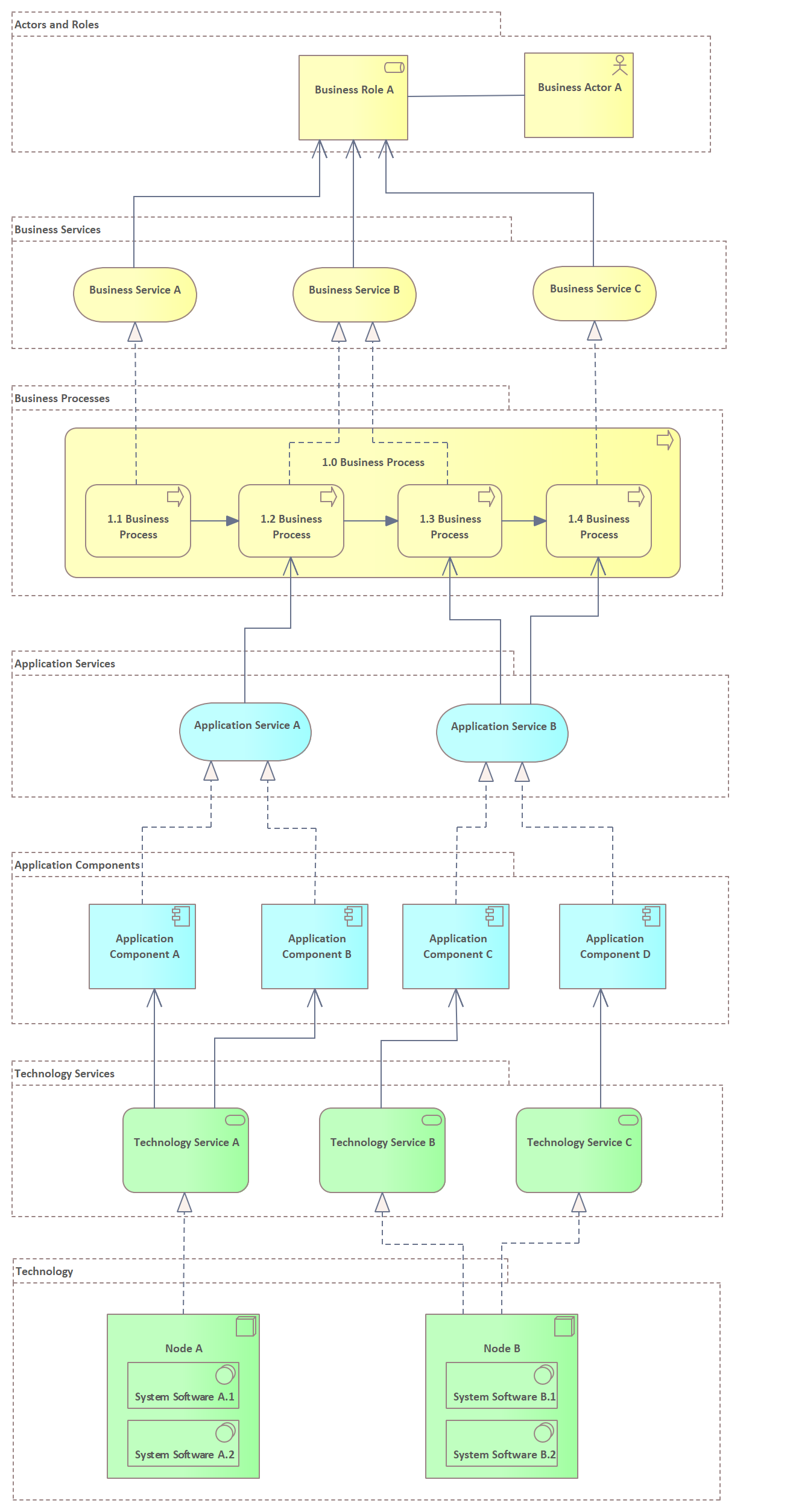
Figure 1. Shows a Business Layer diagram that uses the Grouping element to place elements into meaningful groups.
Discussion
To provide a designing view for Enterprise Architects, Process Architects, Application Architects,Infrastructure Architects and Domain Architects and others who are concerned with aspects such as consistency, reduction of complexity, impact of change, flexibility.
The main use of this viewpoint is to provide an overview of the architecture in a single diagram. It is useful in any situation where a complete or holistic view of all, or a number of models is needed, such as in impact of change analysis, performance analysis or when trying to understand the relationship between concepts in a variety of layers.
The following is a list of some things you may want to do when working with this pattern.
- Change the name of the Package and diagram to suit the initiative.
- Change the names of the Grouping elements to suit the initiative.
- Change the name of all the elements in the diagram to suit the initiative.
- Create additional elements and add other relationship as needed.
The following is a list of next steps you may want to perform after working with this pattern.
- Create trace relationships to up-stream model elements that the elements in this viewpoint ultimately trace back to.
- Create documentation that will help disseminate the information contained in the diagram to other team members.
Motivation Viewpoints
Stakeholder Viewpoint
The Stakeholder Viewpoint pattern creates stakeholders, the internal and external drivers for change, and the assessments (in terms of strengths, weaknesses, opportunities, and threats) of these drivers. Also, the links to the initial (high-level) goals that address these concerns and assessments may be described. These goals form the basis for the requirements engineering process, including goal refinement, contribution and conflict analysis, and the derivation of requirements that realize the goals.
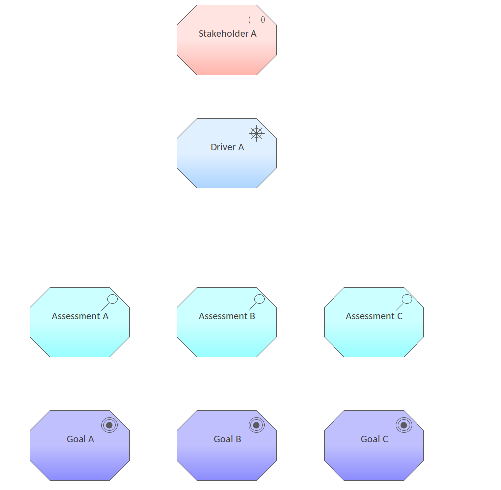
Figure 1. Shows a Motivation diagram that relates Goals through Assessments and Drivers to Stakeholders are concerned about them.
Discussion
The purpose of the pattern is to allow the modeler to create representations of the stakeholders, drivers for change (internal and external), and the assessments (in terms of strengths, weaknesses, opportunities, and threats) of the drivers and the Goals that address the concerns and Assessments.
The pattern is typically used early on in an initiative or definition of an Enterprise Architecture to ensure the right foundation is laid for the Requirements management discipline.
The following is a list of some of the next steps available when applying the pattern.
- Change the name of the Stakeholders, Drivers, Assessments and Goals to suit the initiative.
- Add additional Stakeholders, Drivers, Assessments and Goals as required.
Goal Realization Viewpoint
The Goal Realization Viewpoint pattern creates elements and a diagram that models the relationships between goals including the decomposition to sub-goals. The goals are realized by an Outcome which is realized by a Principle which behaves like a more abstract and broader requirement. Finally the Principle is realized by a Requirement indicating specific properties that the system must exhibit.

Figure 1. Show the decomposition of Goals and their relationship to Principles and Requirements.
Discussion
To provide a designing and deciding view for business managers, enterprise and technical architects, business analysts, requirements managers and other stakeholders who are concerned with the relationship between Goals (and their sub-goals) and the way these are realized by requirements and constraints that define properties the system must exhibit.
The pattern is typically used in the strategic and business design phases of an initiative. The goals and their decomposition and relationship to Principles may be modeled early on and the realizations to Requirements are more commonly modeled as an initiative progresses.
The following is a list of some things you may want to do when working with this pattern.
- Change the name of the Goals, Principle and Requirement to suit the initiative.
- Add additional Goals, Principles and Requirements and add other relationships as required.
The following is a list of next steps you may want to perform after working with this pattern.
- Further decompose the Requirements into more detailed expressions in preparation for further analysis.
- Resolve conflicts or overlaps between the Goals with the appropriate stakeholders ensuring that any changes meet the needs of the entire group of stakeholders.
Goal Contribution Viewpoint
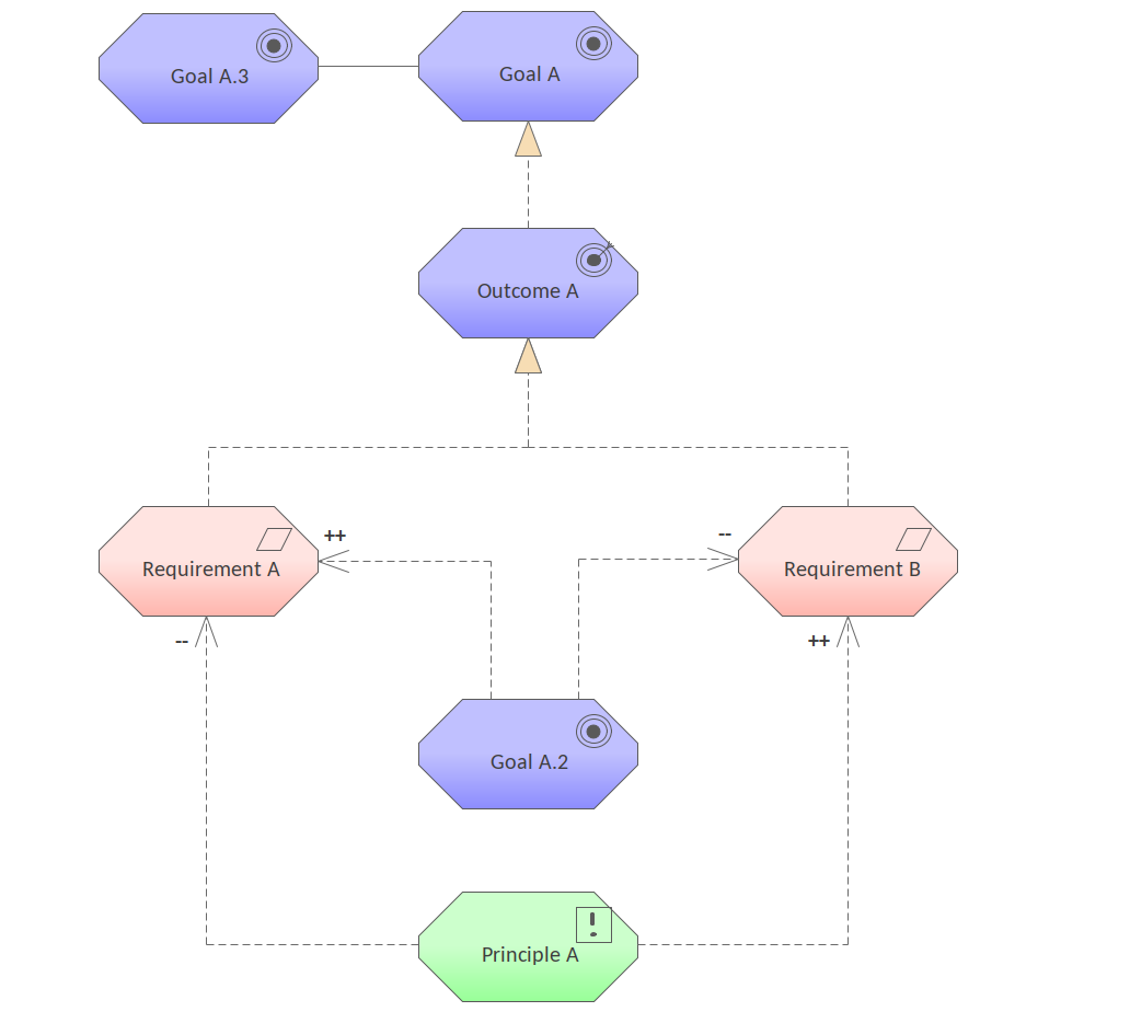
Figure 1. Shows a Motivation diagram showing a number of Influence relationships between Goals, Requirements and Principles.
Discussion
The purpose of the pattern is to allow Business Managers, Business and Requirements Analysis, Architects and other Stakeholders to model and visualize the Influence relationships between Goals, Requirements and Principles.
The pattern is typically used during the analysis phase once goals have been at least defined and partially refined into sub-goals and requirements have started to be defined. It can also be used to analyze the impact that goals have on each other or to detect conflicts between stakeholder goals, allowing them to be addressed and managed.
The following is a list of some things you may want to do when working with this pattern.
- Change the name of the Goals, Requirements and Principles to suit the initiative.
- Add additional Goals, Requirements and Principles as required.
- Add Influence relationships and change existing one to reflect the degree of influence (+,-) by changing the names of the relationships.
The following is a list of next steps you may want to perform after working with this pattern.
- Relate the Capabilities to Drivers and Goals to ensure the Capabilities have a business purpose.
- Relate the Capabilities to Application and Business Services, Functions or Processes as required.
Principles Viewpoint
The Principles Viewpoint pattern creates elements and a diagram that models the relationship between Goals and Principles. Aggregation relationships model the decomposition of Goals and a Realization relationship models how Principles can be related to one or more Goals.
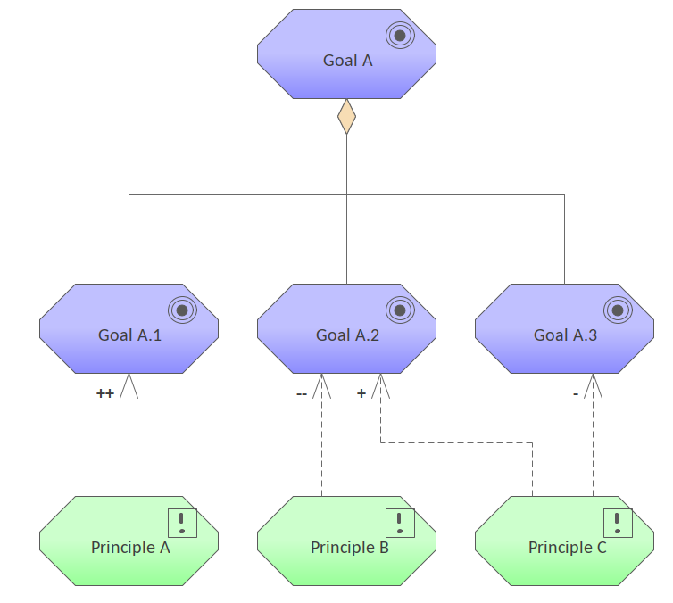
Figure 1. Shows a motivation diagram relating the principles and the goals they implement. Color has been applied to the elements to make the diagram more appealing.
Discussion
The purpose of the pattern is to allow enterprise and information technology architects and other stakeholders to relate Principles back to Goals. The Principles will then form a foundation for the articulation of Requirements.
The pattern is typically used in the early stages of an initiative and will commonly form part of the Enterprise Architecture being reused by a many initiatives.
The following is a list of some things you may want to do when working with this pattern.
- Change the name of the Goals and Principles to suit the initiative.
- Add additional Goals and Principles as required.
The following is a list of some of the next steps available when applying the pattern.
- Goals could be related to each other to show competing forces between stakeholders.
- Principles could be related to each other to show conflicts of architecture.
- Goals could be related to stakeholders to show their provenance.
- Principles could be related to the Requirements that they generalize.
Requirements Realization Viewpoint
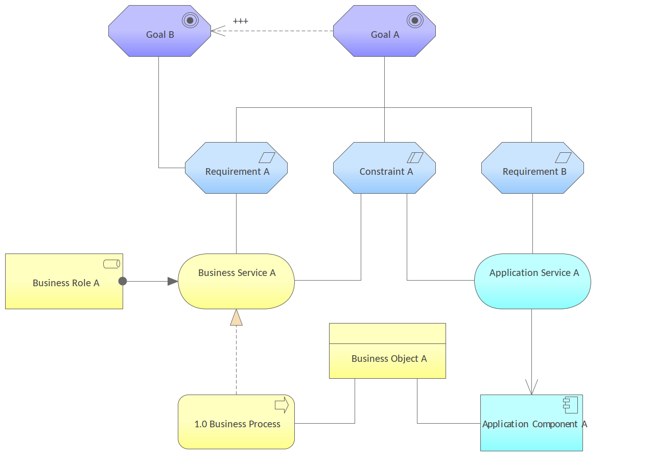
Figure 1. Shows the relationships between Goals, Requirements and the core elements of Business and Application Services.
Discussion
The purpose of the pattern is to allow Enterprise and Business and Technical Architects, Business Analysts, Requirements Managers to model and visualize the way that requirements are decomposed and realized by the elements that represent the services and the elements that implement those services.
The pattern is typically used during the analysis phase when the Goals have been defined and the Requirements and Constraints have been articulated and the Business Services and Process and Application Services and Components have been devised. It can also be used during phases of application or process reevaluation.
The following is a list of some things you may want to do when working with this pattern.
- Change the name of the Goals, Constraint and Requirements, Business Roles and Business and Application Services to suit the initiative.
- Add additional Goals, Constraint and Requirements, Business Roles and Business and Application Services and add other relationship as needed.
The following is a list of next steps you may want to perform after working with this pattern.
- Relate the Drivers and Goals to those of other Stakeholders to determine any conflicts or overlaps that need to be resolved.
- Relate the Requirements to Application and Business Services, Functions or Processes as required.
Motivation Viewpoint
The Motivation Viewpoint pattern creates elements and a diagram that completely covers the motivational aspect from a given stakeholder's perspective defining a Driver, an Assessment, a number of Goals and the Principle that is applied and the Requirements and Constrains that are needed to qualify the Principle.
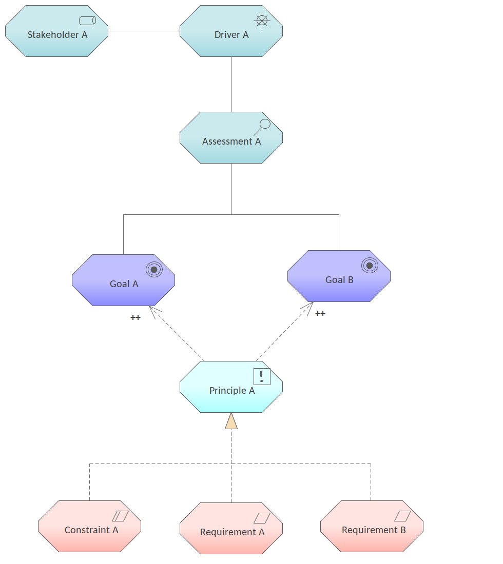
Figure 1. Shows a motivation diagram with a breakdown from a Stakeholder and the elements that define their Goals to the Requirements that specify the behavior a system must exhibit.
Discussion
The purpose of the pattern is to provide a rich view of the motivational aspects of the initiative showing the breakdown from Stakeholders at a high level down to Requirements. It provides a view for Enterprise and Business and Technical Architects, Business Analysts, Requirements Managers and other Stakeholders who are concerned with architecture strategy and tactics and motivation.
The pattern is typically used during the analysis phase of an initiative to gain an overview and insight into how the Requirements and Constraints relate back to the Stakeholders and other things that define their Goals.
The following is a list of some things you may want to do when working with this pattern.
- Change the name of the Stakeholder, Driver, Assessment, Goals, Principle, Constraint and Requirements to suit the initiative.
- Add additional Stakeholder, Driver, Assessment, Goals, Principle, Constraint and Requirements and add other relationship as needed.
The following is a list of next steps you may want to perform after working with this pattern.
- Relate the Drivers and Goals to those of other Stakeholders to determine any conflicts or overlaps that need to be resolved.
- Relate the Requirements to Application and Business Services, Functions or Processes as required.
Strategy Viewpoints
Strategy Viewpoint
The Strategy Viewpoint pattern creates elements and a diagram that models the strategic intent of an organization by articulating a Course of Action and the Capabilities and Resources needed to achieve it providing a modeled Outcome
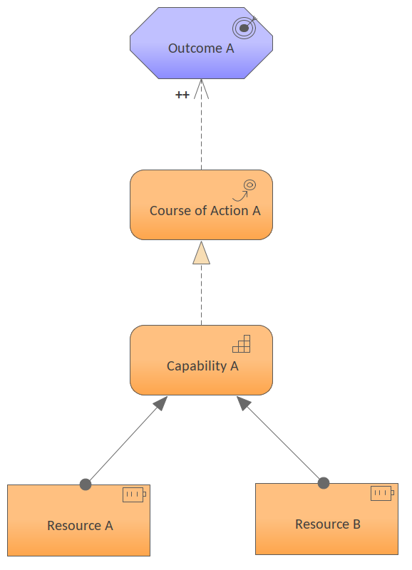
Figure 1. Shows a diagram assigning a number of Resources to a Capability which realizes an outcome that is in turn related to a Course of Action.
Discussion
The purpose of the pattern is to allow business and enterprise architects to model the strategic direction of an organization from a high level by relating it to Capabilities and Resources that provide a demonstrable outcome.
The pattern is typically used at the time the strategies are being formulated as a way of determining how they will be materialized. It may be used at points in the evolution of an organization or its architecture where strategies, courses of action and outcomes are being reviewed or revised.
The following is a list of some things you may want to do when working with this pattern.
- Change the name of the Course of Action, Outcome Capability and Resources to suit the initiative.
- Add additional Outcomes, Capabilities and Resources as required.
The following is a list of next steps you may want to perform after working with this pattern.
- Relate the Course of Action to Goals.
- Relate the Capabilities to Application and Business Services, Functions or Processes as required.
Capability Map Viewpoint
The Capability Map Viewpoint pattern creates elements and a diagram that allows Capabilities to be visualized in a nested hierarchy. The Capabilities are also nested in a hierarchy in the Project Browser allowing groups of them to be easily moved from one location to another. Color has been used to convey the levels of the hierarchy.
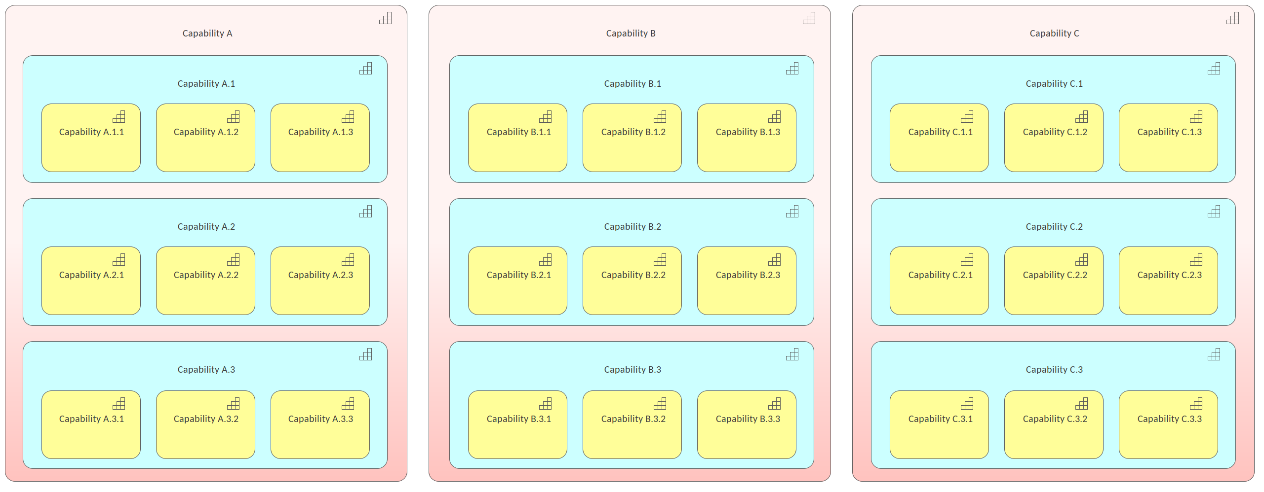
Figure 1. Shows a Capability Map represented as a nested hierarchy, with color applied to the three levels to make the diagram more appealing.
Discussion
The purpose of the pattern is to allow Business Managers, Enterprise and Business Architects and other strategic stakeholders to visualize and categorize the capabilities present or aspired to in an enterprise or one of its parts. It forms a foundation almost every other architectural pursuit.
The pattern is typically crated early on in the definition of the architecture of an enterprise and forms the basis of much of the more detailed work down by other architects. It can also be augmented or changed at strategic points in the evolution of an organization or its architecture.
The following is a list of some things you may want to do when working with this pattern.
- Change the name of the Capabilities to suit the initiative.
- Add additional Capabilities and re-categorize as required.
The following is a list of next steps you may want to perform after working with this pattern.
- Relate the Capabilities to Drivers and Goals to ensure the Capabilities have a business purpose.
- Relate the Capabilities to Application and Business Services, Functions or Processes as required.
Resource Map Viewpoint
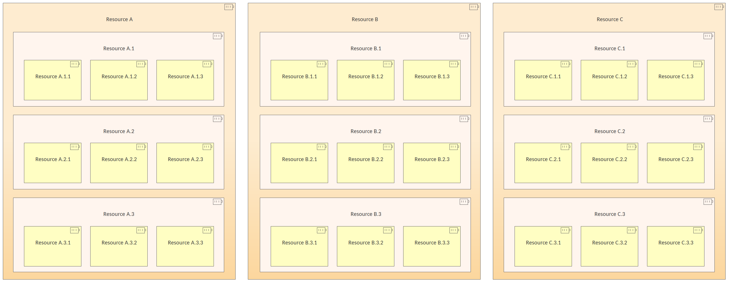
Figure 1. Shows a Motivation diagram that shows a number of nested Resources down to three levels.
Discussion
The purpose of the pattern is to allow a Business Architect or other Stakeholder to create or view an enterprise wide map of the resources and how they are related to each other in a hierarchy.
It is commonly constructed at the time the enterprise architecture is being articulated and can help with planning a number of aspects of the business architecture and implementation including being used as a heat map to identify areas of investment.
The following is a list of some things you may want to do when working with this pattern.
- Change the name of the Package and diagram to suit the initiative.
- Change the name of the Resources to suit the initiative.
- Change the levels of nesting as required.
The following is a list of next steps you may want to perform after working with this pattern.
- Create trace relationships to up-stream model elements that the elements in this viewpoint ultimately trace back to.
- Create documentation that will help disseminate the information contained in the diagram to other team members.
Outcome Realization Viewpoint
The Outcome Realization Viewpoint pattern creates elements and a diagram that model how core elements deliver the high level business value. The diagram is useful to show how the strategic level business elements such as Value and Outcomes are realized by the underlying elements that deliver that value such as Capabilities, Services and Components.
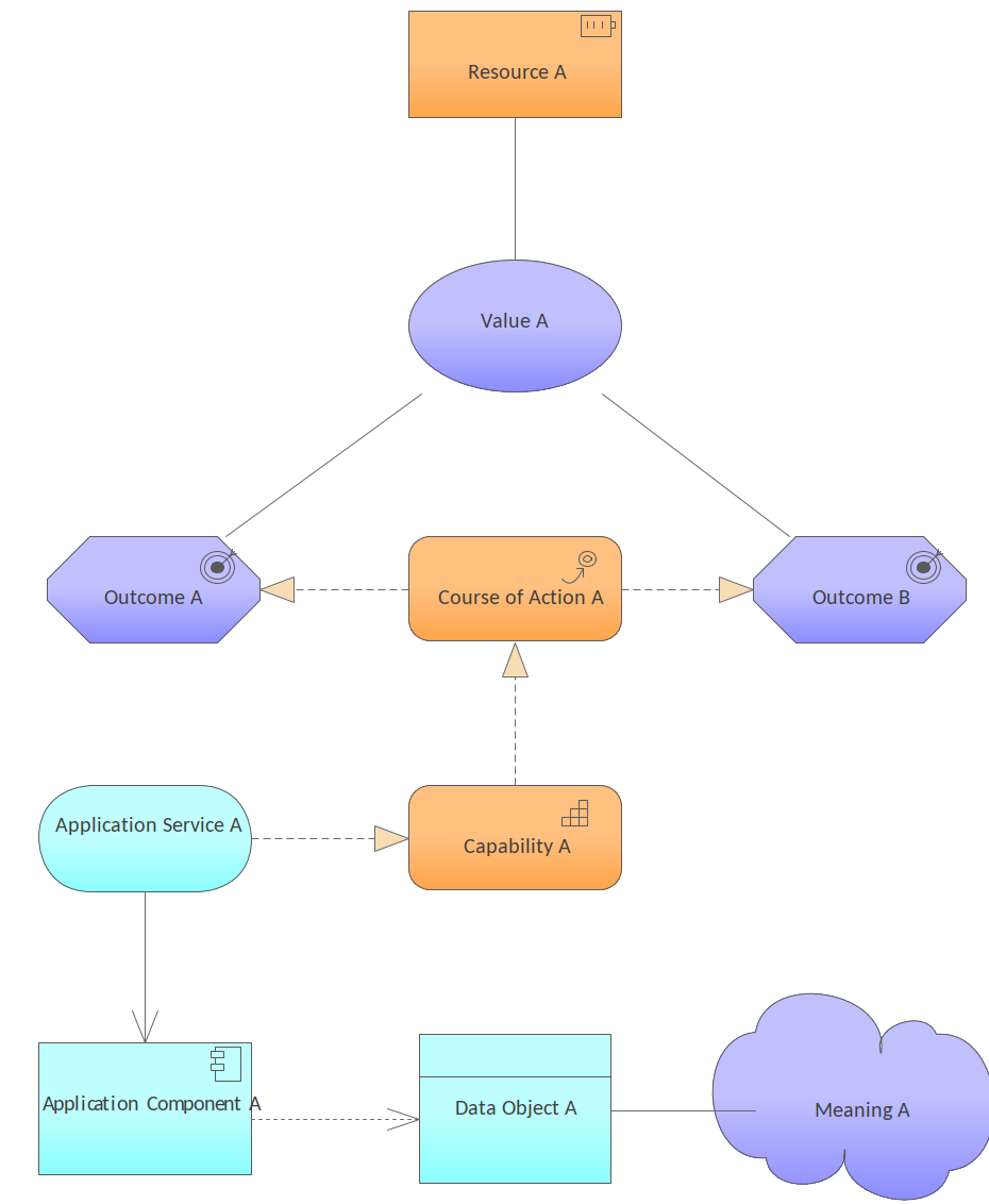
Figure 1. Shows the way core elements deliver the value articulated by the Value element and expressed as Outcomes and a Course of Action implemented by a Capability which in turn is realized by an Application Service and Component.
Discussion
The purpose of the pattern is to allow a Business Managers, Enterprise and Business Architects or other Stakeholder to create or view a model that shows how the high level business outcomes are realized by underlying elements.
It is commonly constructed at the time the enterprise architecture is being articulated and can help with planning a number of aspects of the business architecture and implementation including being used as a heat map to identify areas of investment.
The following is a list of some things you may want to do when working with this pattern.
- Change the name of the Package and diagram to suit the initiative.
- Change the name of the Business level elements to suit the initiative, including: Resource, Value, Outcome.
- Change the name of the underlying elements to suit the initiative, including Application Services and other elements.
The following is a list of next steps you may want to perform after working with this pattern.
- Create trace relationships to up-stream model elements that the elements in this viewpoint ultimately trace back to.
- Create documentation that will help disseminate the information contained in the diagram to other team members.
Implementation and Migration Viewpoints
Project Viewpoint
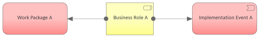
Figure 1. Shows an Implementation and Migration diagram describing the Project Viewpoint.
Discussion
The purpose of the pattern is to allow Operational Managers, Enterprise and ICT Architects, Employees, or other Stakeholder to create or view a model that describes aspects of the transformation from a baseline (current state) to a target (future state). The elements include: Goals, Work packages, Implementation Events, Deliverables, Business Actors, Business Roles.
It is commonly constructed at the time the enterprise architecture change needs to be detailed and has following uses:
- Allows the Strategy teams to understand the enterprise changes in advance.
- Provides detail for the implementation teams that will ultimately instigate the changes.
- Provides details for the Operational Managers who need to understand the impact the change will have on resources.
The following is a list of some things you may want to do when working with this pattern.
- Change the name of the Package and diagram to suit the initiative.
- Change the name of the Work Package, Role and Implementation Event to suit the initiative.
- Create other elements as required.
The following is a list of next steps you may want to perform after working with this pattern.
- Create trace relationships to up-stream model elements that the elements in this viewpoint ultimately trace back to.
- Create documentation that will help disseminate the information contained in the diagram to other team members.
Migration Viewpoint
The Migration Viewpoint pattern creates elements and a diagram that model the transition from a baseline to a target enterprise architecture. The Plateau represents a relatively stable state of the architecture that exists during a limited period of time, whereas the Gap represents a statement of the difference between the two states.
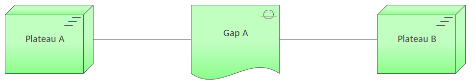
Figure 1. Shows an Implementation and Migration diagram that uses two Plateaus to describe two states of the architecture where the difference is described by the Gap element.
Discussion
The purpose of the pattern is to allow Enterprise Architects, Process Architects, Application Architects, Infrastructure Architects and Domain Architects, Employees, and other stakeholders to model the transitions between different states of the enterprise architecture using Plateaus and Gap elements.
It is commonly constructed at the time a change in the enterprise architecture is being articulated and can help with planning a number of aspects of the business architecture and implementation including being used as a heat map to identify areas of investment.
The following is a list of some things you may want to do when working with this pattern.
- Change the name of the Package and diagram to suit the initiative.
- Change the name of the Plateaux and Gap elements to suit the initiative.
- Add properties and notes to the elements to describe the change in more detail.
- Create additional element as required such as Plateaus and Gap elements.
The following is a list of next steps you may want to perform after working with this pattern.
- Create trace relationships to up-stream model elements that the elements in this viewpoint ultimately trace back to.
- Create documentation that will help disseminate the information contained in the diagram to other team members.
Implementation and Migration Viewpoint
The Implementation and Migration Viewpoint pattern creates elements and a diagram that model relate programs and projects to the parts of the architecture that they implement. This view allows modeling of the scope of programs, projects, project activities in terms of the plateaus that are realized or the individual architecture elements that are affected.
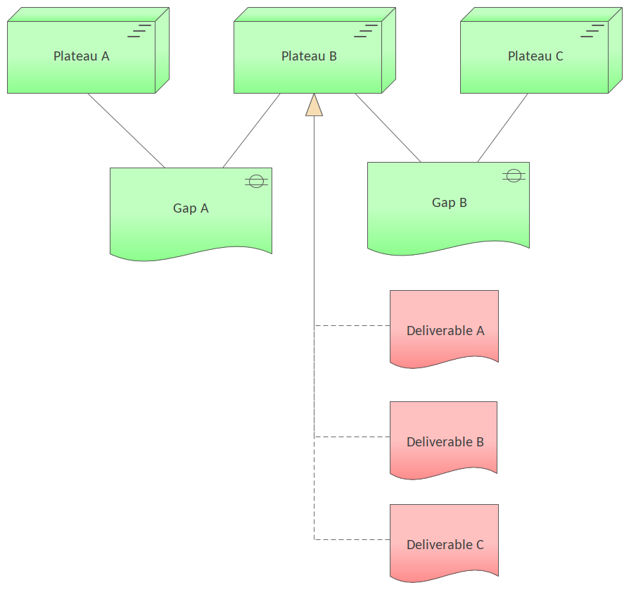
Figure 1. Shows an Implementation and Migration diagram that uses two Plateaus to describe three states of the architecture where the difference is described by the Gap elements. Deliverables relate the Plateaus to architecture elements.
Discussion
The purpose of the pattern is to allow Operational Managers, Enterprise and ICT Architects, Employees, or other Stakeholder to create or view a model that describes the relationship between transitions and the underlying architectural elements that are affected or form part of the architecture.
It is commonly constructed at the time a change in the enterprise architecture is being articulated and can help with planning a number of aspects of the business architecture and implementation.
The following is a list of some things you may want to do when working with this pattern.
- Change the name of the Package and diagram to suit the initiative.
- Change the name of the Plateaux Gap and Deliverable elements to suit the initiative.
- Add properties and notes to the elements to describe the change in more detail.
- Create additional element as required such as Deliverables and other Plateaus and Gap elements.
The following is a list of next steps you may want to perform after working with this pattern.
- Create trace relationships to up-stream model elements that the elements in this viewpoint ultimately trace back to.
- Create documentation that will help disseminate the information contained in the diagram to other team members.
More Resources
Relevant Help Topics
Relevant Enterprise Architect tools
The Pan and Zoom facility is one of the tools that can be used to navigate around a large diagram. Often the resolution of a diagram must be reduced to ensure it is wholly visible but by using the Pan and Zoom window you can leave the diagram at a readable resolution and pan around to areas of interest zooming in when necessary.
The Relationship Matrix provides a spreadsheet like view of two groups of elements and the relationships that exist between them. It can be a used as a powerful analysis mechanism to visually indicate how elements are related to each other and to discover which elements are missing relationships.
The Document Generator is a powerful facility in Enterprise Architect that allows a Database Engineer or other stakeholder to create high quality corporate or technical documentation directly from the model, suitable for internal or external audiences.
The Element Discussion facility is a fully featured collaboration tool allowing modelers and model viewers and reviewers to communicate with each other directly inside the repository. Modelers using the full client or occasional viewers using WebEA can both post and reply to discussions and communicate and engage in chat.
Hand Drawn and Whiteboard Diagrams
Alternate and Images for Diagram Elements
Most standard elements allow an alternate image to be defined for an element that will be used in place of the graphical notation for the element either on a selected diagram or as a default on all diagrams.
ArchiMate is a registered trademark of The Open Group.