| Prev | Next |
Creating Simulink and Simscape Specific Blocks
Given the broad range of different part-types that can be used in Simulink, there will be cases where you need to model Simulink and Simscape parts that you cannot derive from the basic Blocks supplied in the SysPhS Component patterns In such cases you can set a reference in a SysPhS Block to that Simulink component-type. This might be for a Block, a Part or an interface to a Part.
Using the Simulink Class Path for a Block
The process to reference a Simulink component in an Enterprise Architect SysPhS component is:
- In a Simulink diagram containing the component, click on the component and press to access that component-type in the Library
- In the Library window, note the path in the window title, and the Component name under the Component element in the body of the window
- In Enterprise Architect, type the Component path and name into the Properties window, in the 'Name' field under SimulinkBlock ( from SysPhS ):
Here is an example of a Simulink JK Flip-Flop and the 'Parameters' dialog, showing the Class-Path.
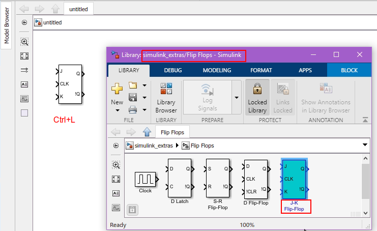
In this case the path/name is:
- simulink_extras/Flip Flops/J-K Flip-Flop
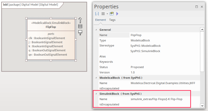
This illustration shows the text added to the Properties window of the SysPhS SimulinkBlock, in the 'Name' field.
For more detail on setting the Simulink Class Path, see the Declaring Member Components 'MathWorks' Help topic.
Using the Simscape Class Path for a Block
The process to reference a Simscape component in an Enterprise Architect SysPhS component is:
- In a Simulink diagram containing the Simscape component, click on the component and press to access that component-type in the Library
- In the Library window, note the path in the window title, and the Component name under the Component element in the body of the window
- In Enterprise Architect, type the Component path and name into the Properties window, in the 'Name' field under SimulinkBlock ( from SysPhS ):
Here is an example of a Simscape component for an Op-Amp.
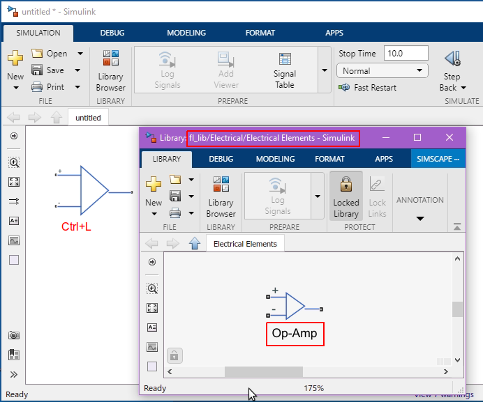
Note that the fl_lib is referenced by 'Foundation', so the SysPhS 'Name' is:
- foundation.electrical.elements.op_amp
Setting the SysPhS Ports
Ports on a Block can be non-typed Ports or predefined Port types.
Non-defined Ports are created by dragging a Simulink Port from the Toolbox onto a diagram.
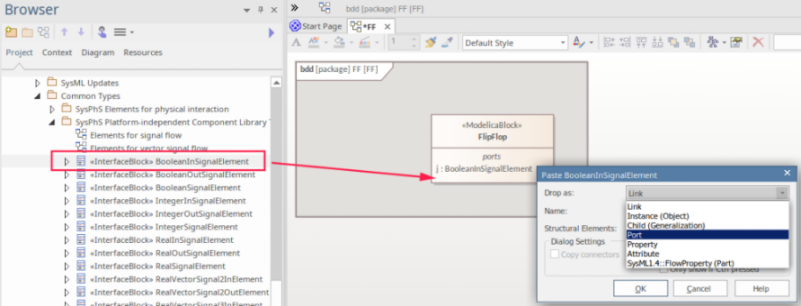
To reference the SysPhS predefined Port-types, such as a boolean signal input port or an analogue signal output port, open the SysPhS Platform Independent Component Library in the Browser window. A Port-type can be dragged onto the Block from the Library and set as a Port on the Block.
For example, this is a snapshot of the process for creating the j and k Ports on the Flip-Flop, showing the j Port set and the k Port in the process of being defined as a Port.
Simulink Port Ordering
Simulink Ports are defined using an array (as opposed to the name reference in Modelica), so the order of creation of the Ports is critical. The ordering of the IN Ports is separate from the ordering of the OUT Ports. Port ordering can be viewed in Simulink; the first Port is shown at the top of the Block.
Using the Flip Flop Ports example, the Simulink ordering of the IN Ports would be:
j, clk, k, (see the 'J-K Flip Flop' element in the first image of this topic)
So, these Ports must be created in Enterprise Architect in that order. Note that the Ports are shown in the Block Definition diagram in alphabetic order, not the order of creation.
A common scenario where ordering has not been applied is when an OUT Port is correctly shown in the SysML diagram, but is incorrectly connected to an IN Port when simulating in Simulink. If this occurs, ensure that the order of creation of the Ports is correctly applied.