| Prev | Next |
Behavioral Models
The behavioral models contain the 'verbs' of the system and define how the system behaves from several different viewpoints.
The Behavior diagrams communicate the behavior of the system and demonstrate how the parts of a system work together to satisfy behavioral requirements. Behavioral models have a range of purposes. The engineer must understand what part of the system's behavior they are modeling and then choose the appropriate tool feature and language construct to model this behavior. Systems Engineers use SysML diagrams to model these behavioral characteristics.:
- Use Case diagrams - used to narrow a system's scope and express the users' goals as a value proposition.
- Activity diagrams - used to define the ordered set of actions that carry the work of the system.
- Sequence diagram - used to show how system components or parts interact to produce an outcome.
- State Machine diagram - used to define the discrete states of a system or its parts during its lifetimes.
Enterprise Architect has a range of productivity tools that the systems engineer can use while working with behavioral models, including the Scenario Builder, State Machine Tables, Simulation engine, and many more.
Use Cases and User Goals
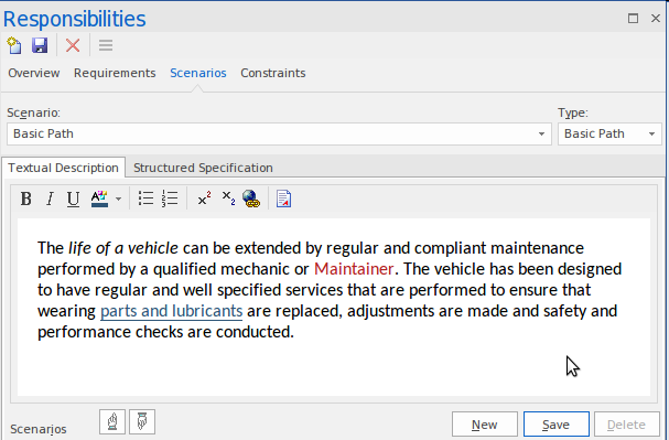
The Use Case model describes the value or goals that users (human and system) derive from interacting with the system. A brief description summarizes this value for each scenario, including the all-important basic (sunny day) scenario.
The Use Case technique is fundamentally straightforward and was devised to ensure that functional requirements were written from the User's perspective. This standpoint helped to ensure that deployed systems would be fit for purpose and be accepted by the diverse community of users. There is, however, a vast amount of conflicting literature and an equally large number of styles for defining Use Cases. This situation has led to confusion and uncertainty and has tended to attenuate the value that can be derived from this simple technique.
Enterprise Architect provides a solution to this by including a purpose-built Scenario Editor that the engineer uses to create detailed descriptions of Use Cases, including alternate and exception paths listing the steps performed by the User and the system.
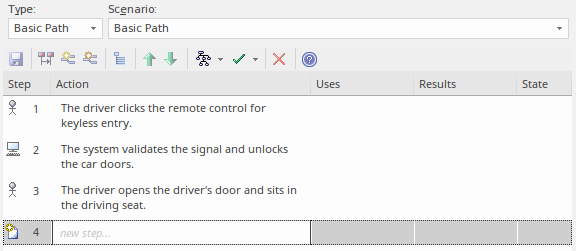
The tool provides a helpful way to generate behavior diagrams such as Activity, Sequence and StateMachine diagrams directly from the scenarios and their steps. These can be synchronized as changes are made to the sequence of steps or to the branch and merge points for alternate and exception scenarios.

Activities and Behavioral Flows
The Activity diagram is an expressive diagram that systems engineers use to show the sequence of actions that describe the behavior of a Block or other structural element. The Actions are sequenced using control flows and can contain input and output Pins that act as buffers for items that flow from one Action to another (or from Control or buffer Nodes). The work carried out by the Actions either consumes or produces these items. The items can be either material, energy, or information, depending on the system and the Activity being described.
Actions are the behavioral atoms that are connected to describe the behavior of an Activity, Sub-system, system, or one of its parts. Effectively an Activity is made up of a set of actions that work together to convert items (tokens) that are input into the Activity to items (tokens) that are output by the Activity. The first Action in a sequence will receive inputs from one of the owning Activity's Input Parameter Nodes. The last Action in the sequence will place the output onto one of the Activity's Output Parameter Nodes. The Actions themselves have input and output devices called Pins - an Action will receive tokens on its Input Pins, perform its work and place the resulting tokens on its Output Pins.
Sequences and Object Interactions
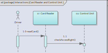
A system is enacted by its parts, working collaboratively to carry out the behavior specified in the behavioral models. Instances of structural elements interact by exchanging messages. These interactions can be specified and visualized using Sequence diagrams that provide a time-ordered set of messages exchanged between participating instances.
In a Sequence diagram, the Blocks that participate in the interaction have a lifetime that is represented by a dashed line, emanating from the base of the element and continuing vertically for the life of the element. Elements can be created or destroyed at any time during the period represented by the Sequence diagram, and the Lifeline therefore represents their existence. Elements that are present at the top of the diagram are created at the beginning of the interaction. A message exchange between a sender and a receiver will originate in one Lifeline (the sender) and end in another (the receiver).
States and Block Lifetimes
The SysML StateMachine is used to describe how structure, modeled with blocks, changes its state in a time-boxed life cycle. Here the engineers' concern is not with the structure of the Block Instance but its behavior, which can, in turn, impact its structure. We are not interested in every single state a 'thing' can exhibit, but rather the significant states. So the critical states for water molecules, for example, could be a solid, liquid, or gas, but we are not ordinarily interested in liquid water at a temperature of 67 degrees Centigrade. If we were looking at a movie reel of an object's lifetime, a StateMachine would pick out the significant frames where significant and relevant changes occurred.
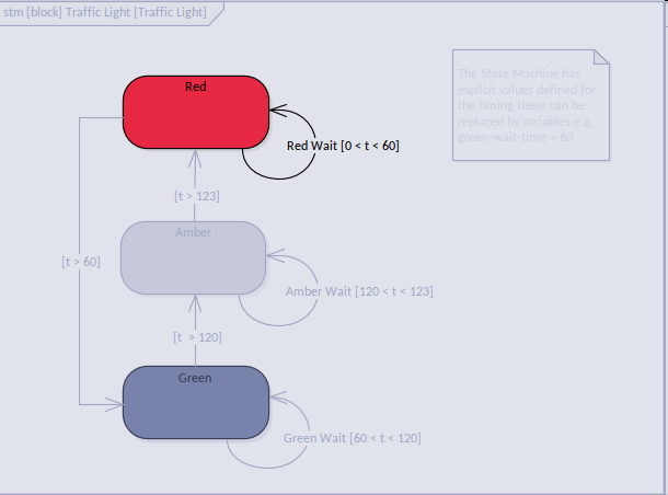
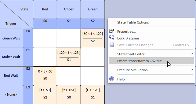
Enterprise Architect also allows an engineer to toggle between diagram and table views of a state machine providing alternative views for engineers and managers who prefer a tabular representation of the state changes. You can also export the tables to a spreadsheet in CSV format for further analysis.
A systems engineer can use state machines to generate executable software code from the model using Executable StateMachines. The code generated is based on its language property. The programming language might be Java, C, C++, C#, or JavaScript; regardless of the language, Enterprise Architect generates the appropriate code immediately ready to build and run.
You can not only generate executable software code, but you can generate Hardware Description Languages and Ada from your model elements, for the chips and circuits in system hardware components.
 in Sparx Systems Enterprise Architect.")