| Prev | Next |
Structural Models
The structural models contain the 'nouns' of the system and define the structures or components of the system. Packages are the primary element for structuring a model or repository and act as containers or namespaces for other elements and their features, including other Packages. The fundamental element of structure is the Block, which can contain both structural and behavioral features and can be used to model any logical or physical aspect of a system. Blocks are typically created and viewed on Block Definition diagrams and also appear on Internal Block diagrams that you use to describe the usage of the Block in a particular context showing the parts that make up the Block. Parametric diagrams are a specialized type of Internal Block diagram used for modeling mathematics and physics equations.
Structure with Packages
The organization of a model is critical to the success of a project or the whole engineering level endeavor. The Package is one of the primary and important elements in the SysML for defining structure. It functions as a container and viewed simply, it is resembles a folder in your favorite file explorer software for your computer. So, in this way, it is firstly a container that groups together other elements, including other Packages but it also has other important functions in Enterprise Architect including for version control, baselining, publications and more.
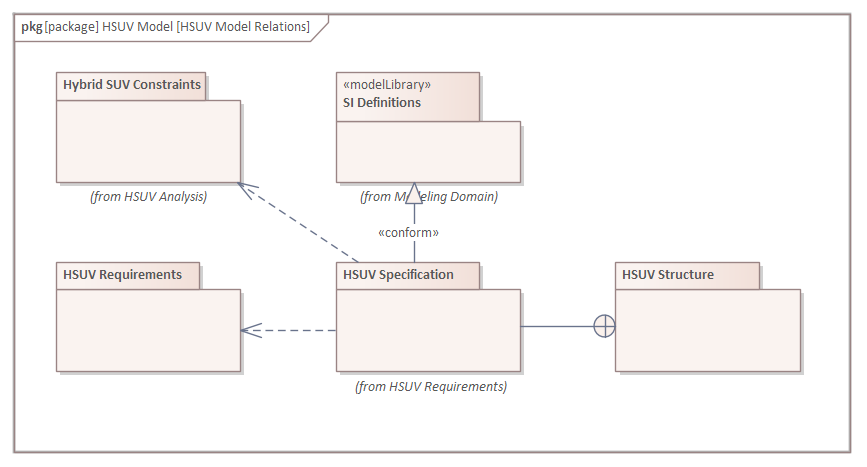
Package diagrams can also be used to visualize the structure of a repository and have the advantage that they can be included in publications or web views of the repository.
Blocks and Constraints
The SysML has similar grammatical categories found in natural languages, with elements that describe structure and other elements that describe behavior. The SysML describes structural things (nouns) using a Block. When engineers create diagrams, they will often use a mixture of behavior or structure elements, describing a particular aspect of a system - bringing to light some aspect of the modeled system.
The Block is the fundamental unit of system structure and is used to describe an entire system, a subsystem, a component, an item that flows through a system, a constraint, or entities that reside outside a system. Similar to our natural languages, a Block can represent something abstract, logical, or physical. This is an important concept, and the SysML writers and readers must be clear about the intention of the representation. For example, in a logical architecture, there are typically Blocks representing conceptual ideas or designs that physical and tangible components might realize at the time of detailed design and construction. A systems architect might define a Block called Collision Detection Subsystem that is an expression of a logical system component that could at the detailed design phase, be in part, realized by a set of radar and laser transmitters, detectors and cameras.
Parts and Block Usage
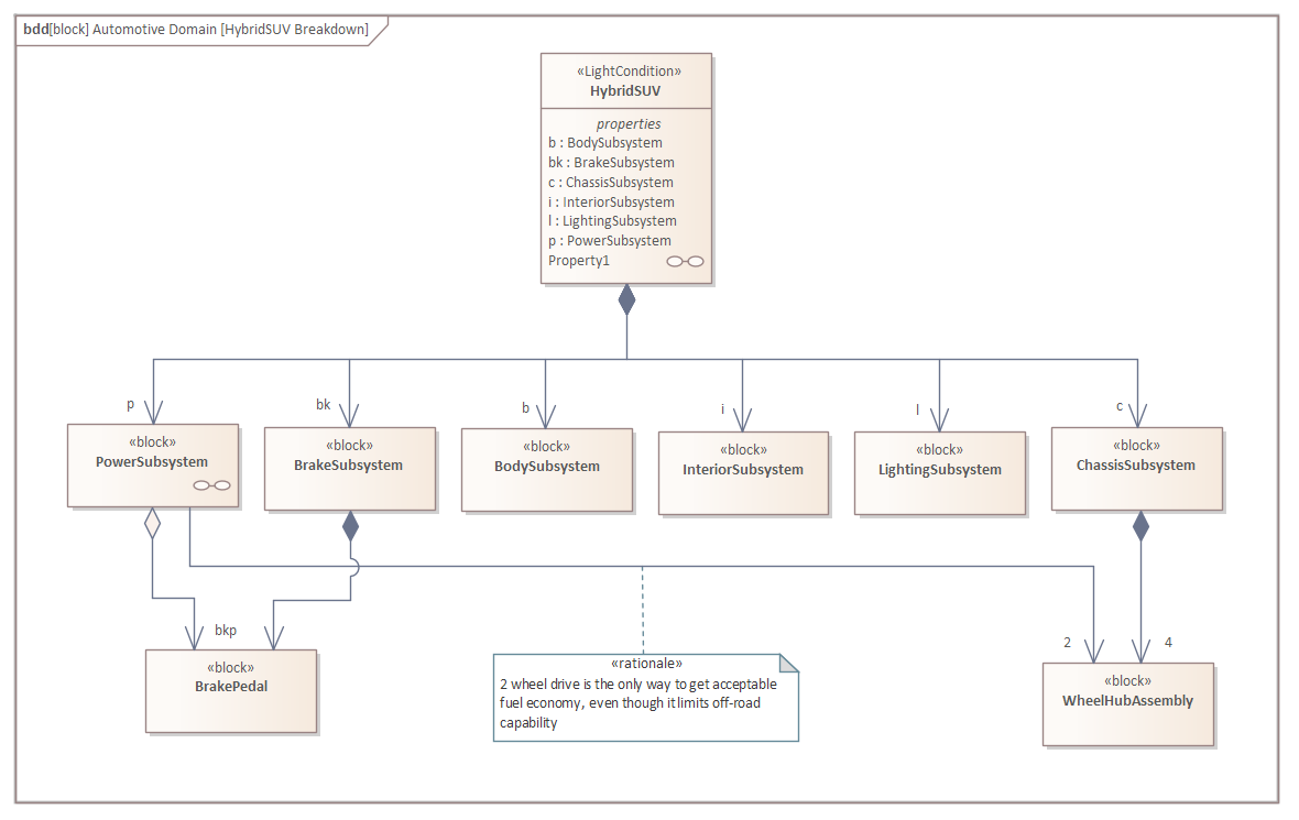
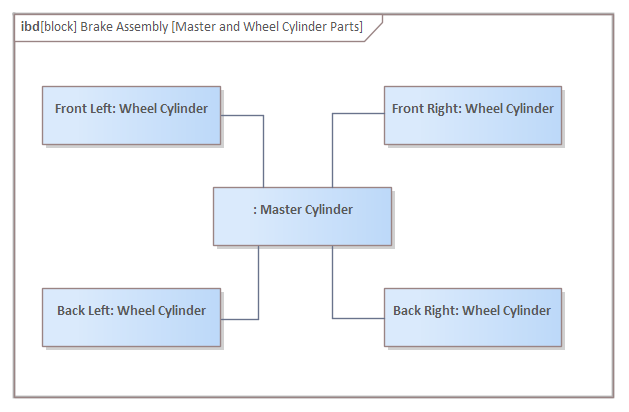
Blocks are classifiers and describe the characteristics of a set of elements that represent how the Block is used in a context. When the Block has attributes (value properties) defined, these are given specific values in the Block instances. Effectively, each Block instance has an identity and typically would have different values assigned that define the Block's state. Enterprise Architect allows these values to be specified using a Set Run State option available from the context menu. Block instances are properties or parts. Thus an engineer working in an automotive domain could define aspects of a vehicle's braking system showing blocks representing a master cylinder's relationship to a wheel cylinder defining a multiplicity of 3..4. The engineer would place instances of these blocks on Internal Block diagrams to express how the parts work together to carry out the behavioral contracts of the system.
The engineer has named each of the wheel cylinder parts (Front Left, Front Right, Back Left, Back Right) as these need to be identified with respect to their location in the vehicle, but has decided not to name the master cylinder as no further qualification is required.
Parametrics and Equations
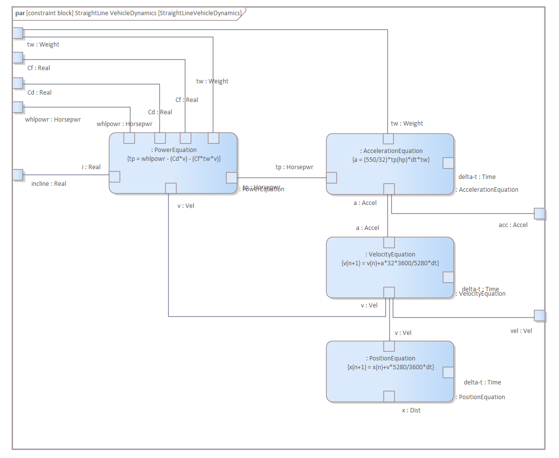
Systems engineering models created in Enterprise Architect provide a valuable tool for analysis, design, architecture, testing, and visualization. Systems Engineers are charged with finding solutions to problems and opportunities and using models to visualize the system's simplifications under consideration and the system's operation context or environment. This includes predicting how a system will behave in a given context, balancing competing requirements and design considerations in the form of stakeholder negotiations and trade-off analysis. Parametric diagrams are a powerful tool that can assist the engineer in addressing these concerns in a model and pre-emptively to represent how a system is likely to behave.
Constraints can be modeled on a block definition diagram and then Parametric diagrams are used to show how theses ConstraintBlocks are used in a particular context, being represented on the diagram as ConstraintProperties. We can visualize how the total power parameter is calculated, connecting the Power Equation and the equivalent parameter on the Acceleration Equation. Connections can be seen between the Position Equation and the Velocity Equation, ultimately connected back to the Acceleration Equation.