| Prev | Next |
Example Models
Transitioning from a document centric approach to a model based systems engineering method can present some hurdles for the newcomer. Fortunately Enterprise Architect has rich and supportive help available and a series of in-tool facilities such as patterns that will get you started with the tool and project models. In this topic we present some straight-forward examples of requirement, structural and behavioral models and the diagrams that you or your colleagues would create in a typical project.
Requirements Models
Requirements models are fundamental to any Systems Engineering project whether be a greenfield project or a change to an existing system. Requirements are typically derived from a number of sources including meetings and workshops with stakeholders, documents or formal and formal requests from sponsors and other project stakeholders. There are a three main types of requirements including high level strategic or business requirements, user requirements and system requirements often referred to as quality attributes of the system.
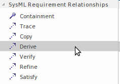
Requirements models will typically evolve over the lifetime of the project and adaptive and iterative methods encourage requirement changes as stakeholders view the partially completed product at critical project milestones. These changes can be represented in the tool in a variety of ways including using the change management functionality available from the construct ribbon. Alternatively these changes can be represented as derivation relationships and visualized in a requirements diagram.
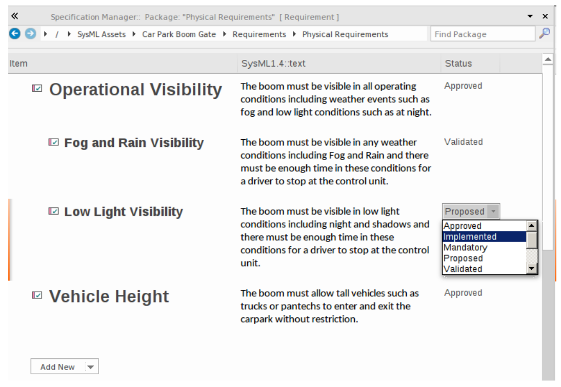
Enterprise Architect provides a rich suite of tools for requirement elicitation, development and management and enforces good requirement engineering practices. One of the key tools for working with requirements is the Specification Manager which allows requirements engineers more familiar with tools like word processors or spreadsheets to work in these familiar paradigms inside Enterprise Architect.
Behavioral Models
A systems engineer can describe how the structural elements of a model behave using a series of diagrams collectively known as the Behavioral model. Structural elements exhibit behavior in a running system, and a number of the structural elements themselves have behavioral features such as operations. The system modeling language specification classifies a number of diagrams as behavior. They are all used to represent different aspects of a system's behavior, from the Use Case that describes behavior that is valuable to a user, to a Sequence diagram that articulates how elements interact.
Use Case Diagram
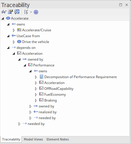
Use Cases and Actors are high-level representations of a system's behavior from the user's point of view. An engineer models the value that a user performing a role with respect to the system derives from the system behavior. A Use Case will typically be traced to other elements such as Requirements and structural elements such as Blocks.
Activity Diagram
Activity diagrams are flow-based models that describe a system's behavior by articulating the flow of items, including information and physical items that act as inputs and outputs to activities and actions as the system performs work.
Sequence Diagram
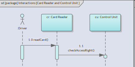
A modeler uses the Sequence diagram to describe the way messages flow between parts and properties of Blocks. The messages are sequenced and are typically implemented by behaviors such as operations owned by the Block.
StateMachine Diagram
A system engineer uses StateMachine diagrams to describe how structural elements such as Blocks behave in response to events that fire and how the states that a Block exhibits a transition from one State to another.
Structural Models
A systems engineer can describe the structure of a system using a series of diagrams that together form the structural model. These diagrams and the elements and relationships they contain, define the components of the system that are bought to life by the behavioral models. The system modeling language specification classifies a number of diagrams as structural. They are all used to represent different aspects of a system's structure at a logical and physical level, from the Packages that organize the model to Parametric diagrams that define equations and their input and output parameters.
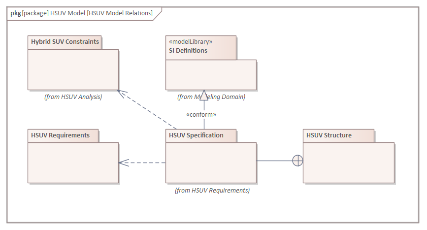
Package Diagram
A complex system must be organized to ensure both humans and other systems can understand, digest, and locate items of interest in the model. Packages that appear in the Browser window can also be placed onto diagrams and are the primary element used to structure the model.
Block Definition Diagram
Blocks are the fundamental structural element in a system's representation; they contain features, exhibit behavior, change states, and interact with other Blocks to produce the behavioral contracts of the system.
Internal Block Diagram
The usage of Blocks and their parts is described on an Internal Block diagram using Parts, Ports, Interfaces and relationships, including flows that describe items that pass between interconnected Blocks.
Parametric Diagram
A property's constraints are defined using Parametric diagrams that model engineering and mathematical equations and their input and output parameters.
Defense and Commercial Architecture Models
A number of frameworks have been used to model large systems or systems-of-systems in defense organizations and large commercial or industrial organizations. These frameworks are based on modeling languages such as the Unified Modeling Language (UML), the Systems Modeling Language (SysML), and Service-Oriented Architecture standards. The frameworks have evolved over several decades as defense, and commercial systems and projects have become larger and more complex. For example, DoDAF and MODAF have been combined to form the basis for the Unified Profile for DoDAF/MODAF (UPDM), and this, in turn, has evolved into Unified Architecture Framework (UAF). Enterprise Architect has rich support for both UPDM and UAF, and systems engineers can create robust, expressive, and compliant defense and commercial models that provide views of complex systems or systems of systems.