

- Resources
- Mapping Use Cases
Mapping Use Cases to Activity Diagrams
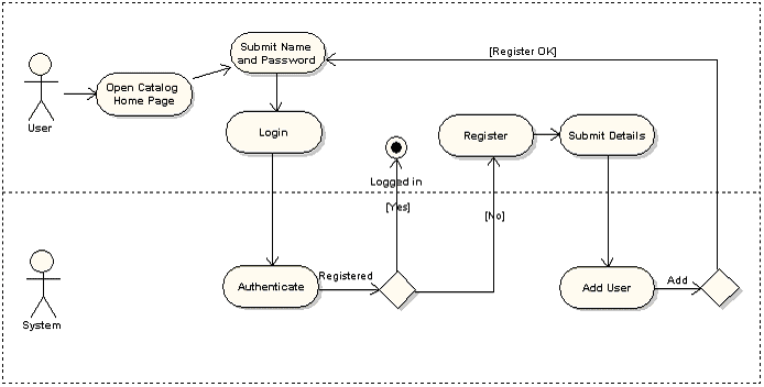
Often, early analysis of business processes will result in a collection of activity diagrams which describe how work is carried out within an organization. This may include dividing the diagram up into logical streams using 'swim lanes' as in the image below.
After this initial analysis work, it can be convenient to group activities into logical Use Cases. Enterprise Architect provides a convenient method of overlaying Use Cases onto activity diagrams while maintaining readability. In the example below, the Use Case 'Login to System' has been overlayed onto the previous diagram.
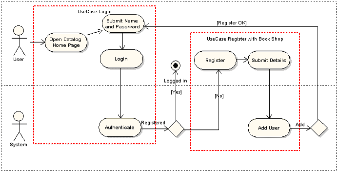
The Red bordered areas above are linked to existing Use Cases by setting the classifier. These 'Use Case Instances' then can be overlayed onto the associated Activities to indicate how particular business process is going to be implemented in the proposed system.
Mapping Use Cases onto Activity Diagrams provides a good means of visualizing the overlay of system behavior onto business process.
To put this into practice on your Activity diagram, create a System Boundary having the same name as the Use Case, and adjust the borders to enclose the Activities represented by the Use Case. Then assign the Use Case as the classifier of the System Boundary. For details, see: http://www.sparxsystems.com/uml_tool_guide/uml_dictionary/systemboundary.html.
If you want to display the Use Case diagram from the Activity diagram, drag the Use Case diagram in the Project Browser into the System Boundary. On the Select Type dialog, click on the Hyperlink option. This creates a hyperlink with the Use Case name, to the Use Case diagram (see the Create Hyperlink Between Diagrams section of http://www.sparxsystems.com/uml_tool_guide/uml_dictionary/hyperlinks.html). Drag the hyperlink to the right of the System Boundary name, single-click three times on the hyperlink name and delete the text. This avoids duplication of the Use Case name.